Lithium Superionic Conductor Li9.42Si1.02P2.1S9.96O2.04 with Li10GeP2S12-Type Structure in the Li2S–P2S5–SiO2 Pseudoternary System: Synthesis, Electrochemical Properties, and Structure–Composition Relationships
 Satoshi Hori
 Kota Suzuki1,2
 Masaaki Hirayama
 Yuki Kato
- 1Department of Electronic Chemistry, Interdisciplinary Graduate School of Science and Engineering, Tokyo Institute of Technology, Yokohama, Japan
- 2Department of Chemical Science and Engineering, School of Materials and Chemical Technology, Tokyo Institute of Technology, Yokohama, Japan
- 3Battery Research Division, Higashifuji Technical Center, Toyota Motor Corporation, Susono, Shizuoka, Japan
- 4Battery AT, Advanced Technology 1, Toyota Motor Europe NV/SA, Zaventem, Belgium
Lithium superionic conductors with the Li10GeP2S12 (LGPS)-type structure are promising materials for use as solid electrolytes in the next-generation lithium batteries. A novel member of the LGPS family, Li9.42Si1.02P2.1S9.96O2.04 (LSiPSO), and its solid solutions were synthesized by quenching from 1273 K in the Li2S–P2S5–SiO2 pseudoternary system. The material exhibited an ionic conductivity as high as 3.2 × 10⁻⁴ S cm−1 at 298 K, as well as the high electrochemical stability to lithium metal, which was improved by the introduction of oxygen into the LGPS-type structure. An all-solid-state cell with a lithium metal anode and LSiPSO as the separator showed excellent performance with a high reversibility of 100%. Thus, oxygen doping is an effective way of improving the electrochemical stability of LGPS-type structure.
Introduction
Lithium batteries have become pervasive in our daily lives, powering portable electronics and power tools, and are expected to play an important role in a vast range of energy storage applications, such as purely electric vehicles and power back-up devices, as well as the grid-level storage of renewably generated energy (Armand and Tarascon, 2008; Scrosati and Garche, 2010; Dunn et al., 2011). These advanced applications will inevitably require batteries that exhibit higher energy and power densities, as well as the ability to be scaled-up. As such batteries undergo improvements in terms of their energy and power densities and size, high-performance electrolytes become essential; a new class of electrolytes must provide high ionic conductivity over a broad range of ambient temperatures and also be thermally/electrochemically stable and compatible with the more reactive electrodes used in the batteries to ensure higher energy and power densities (Jow et al., 2014).
After the discovery of Li10GeP2S12 (LGPS) (Kamaya et al., 2011), which is a new type of lithium superionic conductor, solid electrolytes are expected to satisfy the abovementioned stringent requirements. Consequently, all-solid-state lithium batteries that are based on inorganic solid electrolytes have emerged as attractive options for the next-generation energy storage systems, as they exhibit fewer safety concerns in comparison to battery systems based on flammable organic liquids (Robinson and Janek, 2014; Dudney et al., 2015). Note that the superionic conductor LGPS exhibits a conductivity of 1.2 × 10⁻² S cm−1 at room temperature, which is comparable to or even higher than that of the liquid electrolytes. The high ionic conductivity is attributable to the unique structure of LGPS, in which lithium ions are distributed along the c-axis in a three-dimensional framework composed of an octahedral LiS6 unit and tetrahedral PS4 and GeS4 units (Kwon et al., 2015; Wang et al., 2015).
So far, a number of studies motivated by this attractive feature of LGPS have investigated the charge/discharge performances of all-solid-state cells based on LGPS and have suggested that developing other LGPS-type solid electrolytes would be a significant step toward the realization of all-solid-state batteries with higher power and energy densities (Kato et al., 2012, 2016). However, the following two obstacles need to be overcome before LGPS finds wide application as a solid electrolyte in batteries: the fact that it contains germanium, which is relatively rare and hence expensive, and its low electrochemical stability when in contact with lithium metal. Note that lithium metal exhibits the lowest theoretical potential and a capacity as large as 3860 mAh g−1, which contributes to the increase in the energy density of batteries.
Therefore, the development of LGPS-type solid electrolytes with a high electrochemical stability, reasonably good conductivity, and low cost is desirable. Although previous studies have reported LGPS-type phases in the Li2S–P2S5–SiS2 and Li2S–P2S5–SnS2 pseudoternary systems (Bron et al., 2013; Hori et al., 2014; Kuhn et al., 2014; Whiteley et al., 2014), the electrochemical stability of these LGPS-type materials needs to be improved further. To achieve this goal, we doped oxygen atoms into the LGPS-type structure. The Li2S–P2S5–SiO2 pseudoternary system – Li9.42Si1.02P2.1S9.96O2.04 (LSiPSO) was reported as an LGPS-type phase with promising preliminary results (Kato et al., 2016) – was selected for investigation since SiO2 is a relatively inexpensive and abundant material. We investigated in detail the properties and characteristics of the LSiPSO phase, such as its crystal structure, conductivity, and performance as a solid electrolyte in all-solid-state cell. We found that the oxygen atoms are introduced at specific sites in the LGPS-type structure and that the electrochemical stability is improved significantly but at the expense of a tolerable decrease in the lithium conductivity.
Materials and Methods
Material Synthesis and Characterization
The starting materials, Li2S (Idemitsu Kosan, >99.9% purity) and SiO2 (Kanto Chemical Co. Ltd., >99% purity) powders, were milled to obtain fine particles using a ball-milling apparatus. These starting materials were then weighed together with P2S5 (Aldrich, >99.9% purity) in the appropriate molar ratios in an Ar-filled glove box, placed in a stainless steel pot, and mixed for 90 min using a vibrating mill (CMT, Tl-100). The specimens were then pressed into pellets, placed into a carbon crucible, and then sealed at 10 Pa in a carbon-coated quartz tube. After being heated at a reaction temperature of 1273 K for 5 h, the tube was quenched into ice water. The X-ray diffraction (XRD) patterns of the samples were collected with an X-ray diffractometer (Rigaku, SmartLab) with CuKα1 radiation (λ = 1.5405 Å). The high-temperature XRD patterns were obtained using a high-flux synchrotron X-ray source with a wavelength of 0.5 Å at the B19B2 beamline at the SPring-8 facility in Hyogo, Japan. The measurements were made at temperatures of 300–873 K using a Debye–Scherrer diffraction camera; the specimens were sealed under vacuum in a quartz capillary (ca. 0.5 mm in diameter). Neutron diffraction data were collected using a time-of-flight diffractometer (SPICA) installed on the BL09 beamline at the Japan Proton Accelerator Research Complex in Tokai, Japan. The specimens were sealed in a vanadium cell (ca. 6 mm in diameter) with an indium ring. The software program Z-Rietveld was used to refine the structural and profile parameters (Oishi et al., 2009). Differential thermal analysis (DTA) was performed using a Rigaku Thermo plus TG8120 system at temperatures between room temperature and 1173 K.
Electrochemical Measurements
The test cell used in this study for the electrochemical measurements has been described previously (Kobayashi et al., 2008). The ionic conductivity was measured by the AC impedance method in an Ar atmosphere at temperatures of 248–373 K. A signal with an amplitude of 100 mV and frequencies between 1 Hz and 10 MHz was applied using a frequency response analyzer (Solartron, 1260). The sample powder was pressed into a pellet in a cylinder. The electrodes were prepared by pressing an Au powder at 444 MPa onto both sides of the pellet. The electrochemical window of the solid electrolyte was evaluated using cyclic voltammetry. The asymmetric Li/solid electrolyte/stainless steel cell was examined with a scan rate of 1 mV s−1 and voltages between −0.1 and 5 V using a Solartron 1287 electrochemical interface. The solid-state cells were constructed using the synthesized solid electrolyte as the separator, a mixture of LiNbO3-coated LiCoO2 and LGPS as the composite cathode (7:3 in weight ratio), and Li metal (thickness: 0.3 mm, diameter: 5 mm) as the anode (Ohta et al., 2007; Li et al., 2016). Besides LSiPSO, three LGPS-type materials (such as LGPS, Li10.35Si1.35P1.65S12, and Li9.81Sn0.81P2.19S12) were used as separators for comparison purpose. Each of these electrolyte powders of 200 mg was pressed into a pellet in an insulator tube. The composite cathode of 2–3 mg was then pressed onto one side of the separator-pellet, and Li metal foil was attached onto the other side. Cycling tests were performed at 2.55–4.25 V using a charge/discharge testing machine (TOSCAT-3100, Toyo System). The current applied to the cell was 7.25 mAh g−1 (0.05 C rate), which corresponded to current densities of 0.015–0.019 mA cm−2. The specific capacities of the cells were calculated based on the weight of the LiNbO3-coated LiCoO2 sample.
Results and Discussion
Synthesis
Figure 1 shows the Li2S–P2S5–SiO2 pseudoternary diagram along with the compositions at which the samples were obtained. Since the solid-solution ranges for the LGPS-type phases have been reported to exist in the Li4 MS4–Li3PS4 system (M = Si, Ge, Sn) (Hori et al., 2014, 2015a), we investigated the compositions on the Li4SiS2O2–Li3PS4 tie line (samples #2–4) and those surrounding the tie line (samples #1 and #5–10).
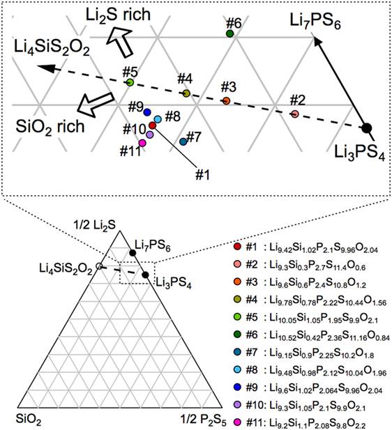
Figure 1. Composition diagram for the Li2S–P2S5–SiO2 pseudoternary system. The compositions synthesized in this study are indicated along with the related label numbers in the magnified view of the diagram. The compositional formulas corresponding to these label numbers are also shown on the lower right-hand side.
The XRD patterns of the synthesized samples are shown in Figure 2. All the diffraction lines for the sample with the nominal composition, LSiPSO (sample #1), which was synthesized as described in Section “Materials and Methods,” were indexed to the same space group as that of the original LGPS phase [P42/nmc (137)], indicating that the LSiPSO phase had a LGPS-type structure. We tested various synthesis conditions and found that although the optimized mixing procedures and cooling rates are important for obtaining monophasic LSiPSO (see Figure S1 and Table S1 in Supplementary Material), the composition is more relevant with respect to the phase that appears in the samples. In the case of the compositions on the Li4SiS2O2–Li3PS4 tie line, the LSiPSO phase was not obtained as a pure phase; the main phases were a β-Li3PS4-derived phase in samples #2 and #3, a LSiPSO phase along with the Li7PS6 phase with an argyrodite-like structure in sample #4, and a Si-based LGPS-type phase in sample #5 (Kong et al., 2010; Homma et al., 2011). For compositions derived from the Li4SiS2O2–Li3PS4 tie line, the phases that appeared changed with the amount of SiO2 in the composition; for the samples with smaller amounts of SiO2 compared to the case for sample #4, the Li7PS6 phase and a β-Li3PS4 modification were observed as the main primary phases in the samples #6 and #7, respectively. When the amount of SiO2 in the compositions was increased from that in sample #4, the volume fraction of the LSiPSO phase also increased (samples #8–11). Since samples #8 and #11 exhibited impurity phases such as γ-Li3PS4 and a crystalline SiO2 phase, it was concluded that the solid-solution range for the LSiPSO phase exists for compositions very similar to LSiPSO in the Li2S–P2S5–SiO2 pseudoternary system. The detected phases for each sample are listed in Table 1 along with the synthesis parameters.
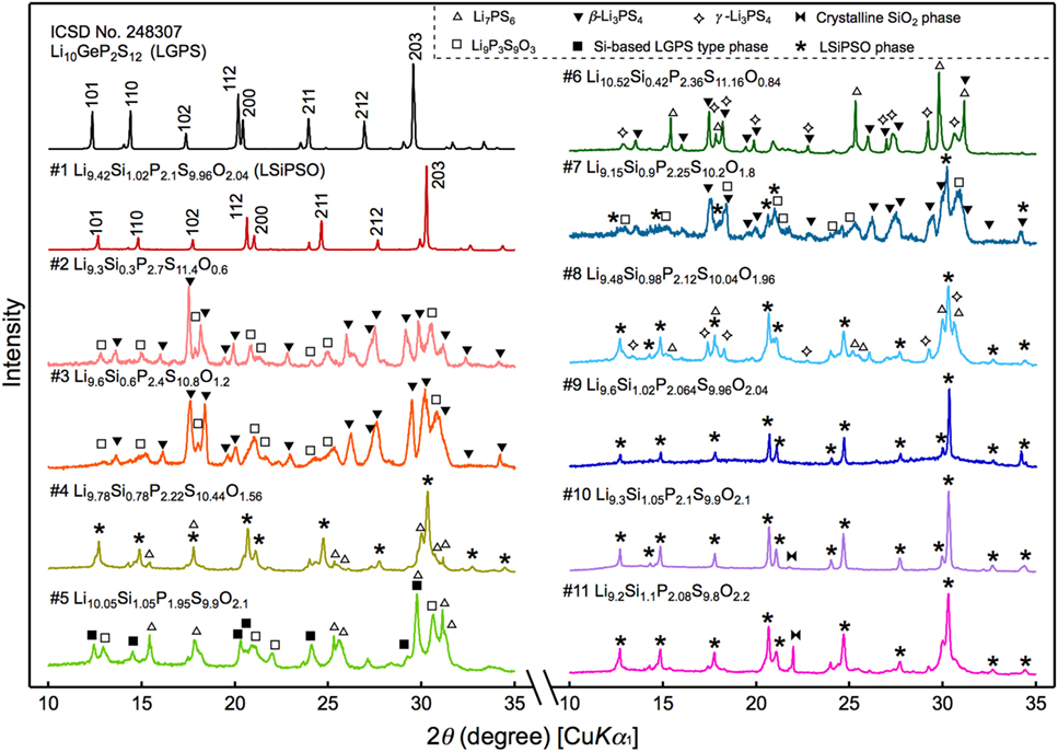
Figure 2. X-ray diffraction patterns for the synthesized samples and that of the original LGPS phase. The sample numbers and compositions correspond to those shown in Figure 1.
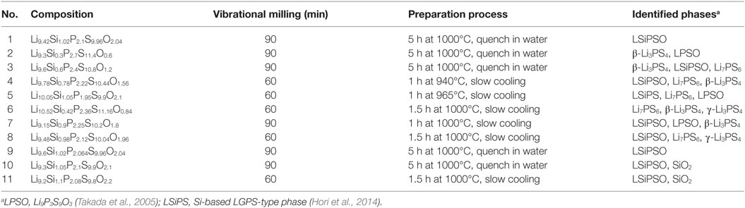
Table 1. Methods used to prepare the various samples in the Li2S–P2S5–SiO2 system synthesized in this study.
Ionic Conductivity
The conductivity was measured by the AC impedance method using a pressed sample of powdered LSiPSO. The highest temperature during the measurement was restricted to 373 K, owing to experimental limitations; however, the thermal and high-temperature XRD analyses indicated that LSiPSO was stable at even 573 K (see Figure S2 in Supplementary Material). Figure 3 shows the Nyquist and Arrhenius plots for LSiPSO. The impedance plots at and below 298 K consisted of a semicircle in the high-frequency range and a spike in the low-frequency range. The spike is considered due to formation of a double layer in the electrolyte/Au electrode interface (Irvine et al., 1990). The inset in Figure 3A shows the equivalent circuit used for simulating the data at and below 298 K. It consists of a resistance and constant-phase element (CPE) in parallel, with the two being in series with a CPE; these, respectively, represent the combined effects of the bulk and the grain boundaries and the effect of double-layer capacitance. The capacitance value for the high-frequency semicircle was calculated to be 1.2–1.5 × 10⁻¹⁰ F (see Table S2 in Supplementary Material). Since the bulk and grain-boundary capacitances are empirically considered to be of the order of 10−12 and 10−9 F, respectively, the capacitance values indicated that the observed semicircles were ascribable to the fact that the grain boundaries contributed more to the resistance than did the bulk (West, 1984; Irvine et al., 1990). The shape of the impedance plots above 298 K was no longer semicircular, and the spike from the electrode contribution was observed; the intercept to the real axis was used for calculating the electrical conductivity. The ionic conductivity of LSiPSO was 3.2 × 10⁻⁴ S cm−1 at room temperature. This value is one order of magnitude smaller than that of LGPS, which shows the ionic conductivity of 1.2 × 10⁻² S cm−1 for a sintered pellet (Kamaya et al., 2011) or 6–8 × 10⁻³ S cm−1 for a cold-pressed pellet (Kato et al., 2012; Shin et al., 2014; Han et al., 2015). Nevertheless, the ionic conductivity value of LSiPSO meets the conductivity criterion (>10−4 S cm−1) proposed for practical electrolytes in lithium batteries (Goodenough and Kim, 2010). The activation energy was calculated as being 33.7 kJ mol−1, which is larger than that for other LGPS-type phases reported previously (25–26 kJ mol−1) (Kato et al., 2016). In general, oxides show larger grain-boundary resistances than do sulfides; we assume that the higher activation energy observed for the LSiPSO phase is ascribable to the larger resistance of the grain boundaries, which is the result of the oxide doping. This assumption was consistent with the fact that the capacitance value observed at 298 K was closer to the typical value of the grain-boundary capacitance than that of the bulk capacitance. The ionic conductivity would potentially be increased by the optimization of the annealing conditions, which would reduce the grain-boundary resistance.
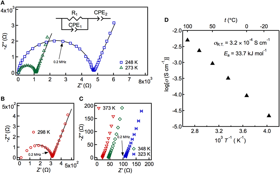
Figure 3. Impedance plots (A–C) and Arrhenius plots of the conductivity data (D) measured at 248–373 K. The solid line in the left panel shows the fit obtained using the equivalent circuit (inset), which was composed of the total resistance and the constant-phase elements (CPEs), which, in turn, represent the combined response of the bulk and the grain boundaries, and the electrode response.
Electrochemical Stability
In the present study, we studied in detail the electrochemical stability of LSiPSO, which had been explored briefly in a previous study (Kato et al., 2016). The charge/discharge performance of a solid-state cell using LSiPSO and examined at 298 K is shown in Figure 4. The inset in Figure 4A shows a schematic drawing of the cell used in this study. The cell consists of the synthesized solid electrolyte as the separator, a composite of LiNbO3-coated LiCoO2 with LGPS as the cathode composite material, and Li metal as the anode. Figure 4A shows the charge/discharge curves of the cells using a different LGPS-type solid electrolyte such as the original LGPS phase (LGPS) and Si-/Sn-based isostructural phases such as Li10.35Si1.35P1.65S12 (LSiPS), Li9.81Sn0.81P2.19S12 (LSnPS), and LSiPSO. The capacity was calculated based on the weight of LiCoO2 powder in the cathode composite. The plateau regions of the charge/discharge curves during the first cycle at approximately 3.9 V for all the cells probably correspond to the lithium extraction/insertion reaction of LiCoO2. The test cell with LSiPSO exhibited an initial discharge capacity of ca. 100 mAh g−1, which is larger than those reported for all-solid-state cells using a sulfide-based electrolyte and cathode and anode materials similar to those used in the present study (Takahara et al., 2004). Furthermore, LSiPSO exhibited high electrochemical stability during cycling. The discharge capacity of the LSiPSO cell remained higher than 95 mAh g−1 (>98% of the initial capacity), whereas the LMPS (M = Si, Ge, Sn) cell showed a rapid capacity fading, with the capacity eventually dropping to less than 20% of the initial discharge capacity, as shown in Figure 4B. Moreover, the charge/discharge reversibility calculated from the discharge/charge capacity ratio, which is given in Figure 4C, also confirmed the better performance of the cell with LSiPSO; the efficiency of the LSiPSO cell reached almost 100% after the second cycle while LMPS showed much lower efficiency.
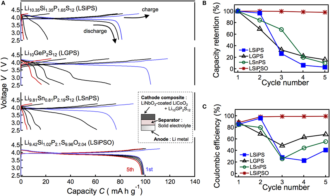
Figure 4. Results of the charge/discharge tests of the all-solid-state cell consisting of a LiNbO2-coated LiCoO2 cathode, Li9.42Si1.02P2.1S9.96O2.04 (LSiPSO) as the electrolyte, and a Li metal anode. The figure also shows the data for cells with Si-, Sn-, and Ge-based LGPS-type solid electrolytes as the separator. The left panel shows charge–discharge curves (A) and right panels show the capacity retention (B) and coulombic efficiency (C) as functions of the cycle number.
Previous studies have proposed that the performance of all-solid-state cell using Li anode is closely related to the continuous growth of the interphase formed by reductive decomposition of the solid electrolyte on the Li electrode (Kanno et al., 2004; Takahara et al., 2004). We presume that the capacity fading of the LMPS cell is due to overpotentials during charge–discharge processes, which could be observed when an interphase with low ionic conductivity continuously grows with cycling (Kanno et al., 2004; Whiteley et al., 2014). The irreversibility of the LMPS cell can be ascribed to the larger overpotential during discharge process than that during charge process (Whiteley et al., 2014); the cell voltage was dropped down to the cut-off voltage by the overpotential before the discharge of the cell was completed.
On the other hand, charge–discharge characteristics can be improved by generating stable interphase between anode and solid electrolyte, as demonstrated in previous studies (Kanno et al., 2004; Takahara et al., 2004). The excellent performance of the cell with LSiPSO suggests that the LSiPSO phase has stability to reductive decomposition on Li electrode and/or forms a stable interphase on Li electrode and, therefore, is expected to find application in high-energy density all-solid-state batteries using Li metal electrodes. Charge–discharge tests at high temperatures to demonstrate rate capabilities of the all-solid-state cell with LSiPSO are planned for future works.
To elucidate why the solid-state cell with LSiPSO exhibited better performance than those with the other LGPS-type solid electrolytes, the electrochemical window was examined by cyclic voltammetry using a lithium metal electrode as the reference. Figure 5 displays current–voltage curves for LSiPSO as well as the other LGPS-type electrolytes. No significant current was observed till voltages of up to 5 V (vs. Li+/Li) with respect to all the solid electrolytes. In addition, the shapes of the CV curves at 3–5 V did not change significantly over five cycles, indicating electrochemical stability with respect to oxidation when in contact with cathode materials having a high electrochemical potential (4–5 V vs. Li/Li+). This experimentally observable stability toward oxidation is considered due to formation of a passivation layer between a solid electrolyte and electrode (Han et al., 2015; Richards et al., 2016). Cathodic and anodic currents were observed near 0 V (vs. Li+/Li), these were partly owing to the lithium deposition reaction (Li+ + e− → Li) and the dissolution reaction (Li → Li+ + e−), respectively. However, the cathodic current near 0 V could also be ascribed to the reductive decomposition of the solid electrolyte or the interfacial reactions that occur on the Li electrode, while the anodic current was probably attributable to the corresponding reverse reactions. In the case of LSiPSO, the cathodic current was observed at below 1.5 V, suggesting a reaction of LSiPSO at the electrolyte/electrode interface starts at this voltage. On the other hand, the ratio of the peak areas of anodic/cathodic current, which potentially indicates reversibility of the deposition–dissolution reaction (Kondo et al., 1992), was much higher than that in the case of the other LGPS-type electrolytes. Moreover, while the shapes of the CV curves of the other LGPS-type materials changed significantly near 0 V over five cycles, the CV curves of LSiPSO underwent no significant change. These observations suggested the interfacial reaction of LSiPSO, and Li deposition–dissolution reactions were more reversible than those corresponding reactions in the case of the other LGPS-type materials. This assumption is consistent with our observation that the all-solid-state cell with the LSiPSO phase showed greater performance than those with the other LGPS-type materials.
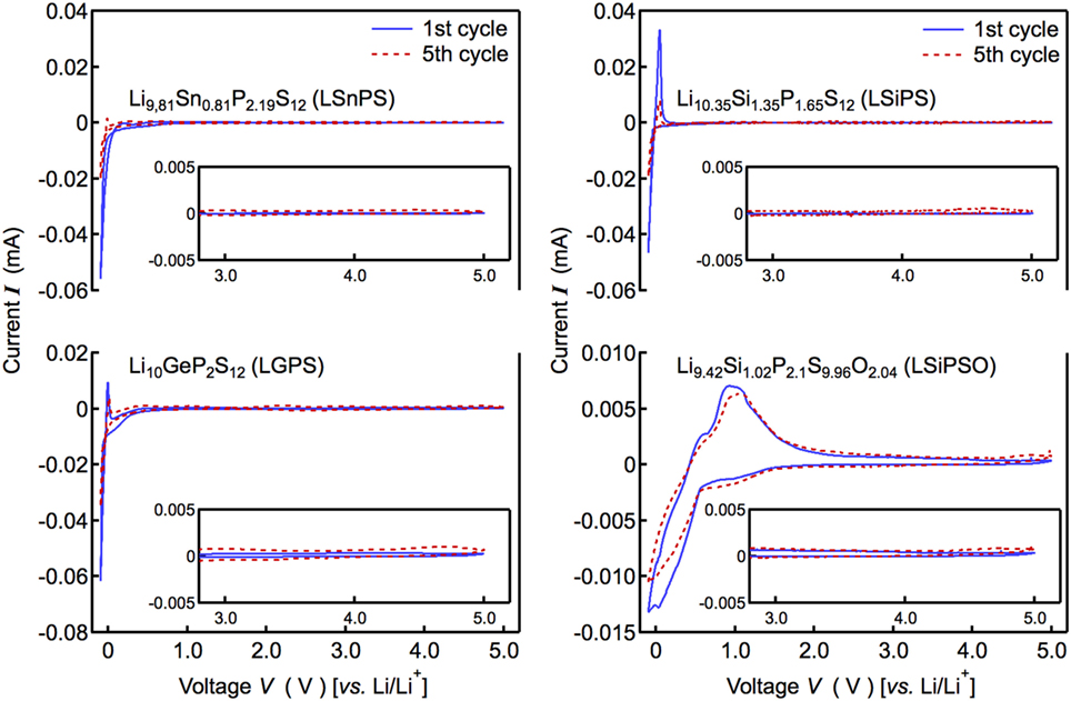
Figure 5. Current–voltage curves of the Li/Li9.42Si1.02P2.1S9.96O2.04/stainless steel cell. The figure also shows the data corresponding to the Si-, Sn-, and Ge-based LGPS-type solid electrolytes.
Structure Analysis
The crystal structure of LSiPSO was analyzed based on the neutron diffraction data using the Rietveld refinement. In this study, the structure of LSiPSO was analyzed based on the original LGPS composition; Li10SiP2S10O2 was used for the structural analysis.
Figure 6 shows a schematic drawing of the crystal structure based on the analysis. The details of the refinement results are described in Figure S3 and Tables S3 and S4 in Supplementary Material along with the refinement process. The lattice parameters for LSiPSO were calculated to be a = 8.43126 (4) Å and c = 12.3666 (9) Å; these are smaller than those of the LGPS and LGPS-type phases in the Li–Si–P–S system, indicating that all the Ge (ionic radii r = 0.39 Å) atoms and some of the S atoms (r = 1.84 Å) were substituted with Si (r = 0.26 Å) and O atoms (r = 1.40 Å), respectively (Shannon, 1976; Hori et al., 2014). The Li ions were in the Li1 and Li3 sites distributed along the c-axis; this was in keeping with the original LGPS model. Moreover, these sites showed larger atomic displacement parameters than those of the Li2 and Li4 sites, suggesting that, in the case of LSiPSO, the Li1 and Li3 sites play an important role in lithium conduction, which is the conduction mechanism of LGPS as observed experimentally and suggested by previous theoretical studies. The O atoms were found to selectively occupy one of the three 8g sites (the site for S1); 76% of the total O atoms in the structure occupied the vertices of the P2[S/O]4 tetrahedra, which connect the polyhedral chains along the Li1 and Li3 sites. The average [Si1/P1]–[S/O] distance in the [Si1/P1][S/O]4 tetrahedra (: 2.046 Å) was smaller than that for Si-based LGPS-type phase (: 2.094 Å) (Hori et al., 2015b), indicating the introduction of O atoms, which possess a smaller ionic radius than S atoms. The average P2–[S/O]4 distance (: 1.789 Å) showed a significant decrease in comparison to the corresponding P2–S distance for the Si-based LGPS-type phase (: 2.005 Å); this corresponded to the selective substitution of oxygen atoms at the S1 site.
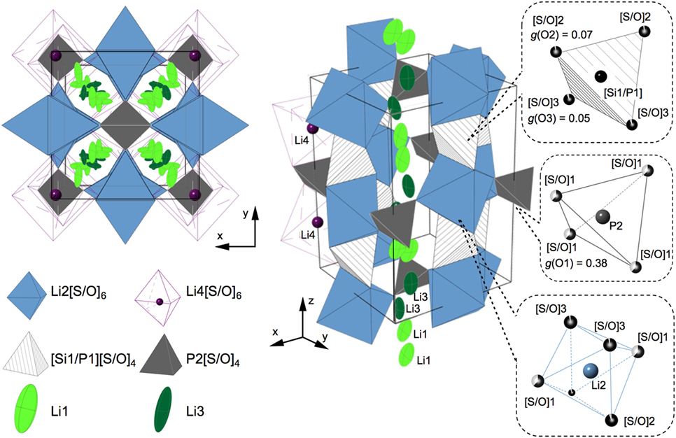
Figure 6. Schematic drawings of the LSiPSO crystal structure determined by Rietveld analysis. The structure is represented by polyhedrons and ellipsoids; the blue and purple octahedra represent Li2(4d)[S/O]6 and Li4(4c)[S/O]6, respectively; the hatched and dark gray tetrahedra represent [Si1/P1][S/O]4 and P2[S/O]4, respectively; Li1(16h) and Li3(16h), which show large atomic displacement parameters, are drawn with a 50% probability as light- and dark-green ellipsoids, respectively. Li1 and Li3 are distributed along the c-axis in the framework composed of Li2[S/O]6 octahedra, [Si1/P1][S/O]4 tetrahedra, and P2[S/O]4 tetrahedra. The left side shows the top view from the c-direction. The right side shows a perspective view, in which parts of Li1, Li3, and Li4 are not drawn for simplicity. The coordination of the sulfide/oxide atoms in the polyhedral is indicated in the dotted rectangles along with the occupation parameters, g, for the oxide atoms.
The doping of O atoms caused a decrease in the lattice parameters, which is often unfavorable for lithium conduction. The doped O atoms occupied vertices of the tetrahedra located at the centers of the tunnels along the c-axis, in which lithium atoms are distributed (Figure 6). These positions of the doped O atoms and the lowering of the conductivity of LSiPSO in comparison to that of the original LGPS phase supported the assumption that the tubes along the c-axis are the primary conduction pathways for lithium ions, as has also been proposed by experimental research as well as theoretical studies (Kwon et al., 2015; Wang et al., 2015). With respect to electrochemical stability, the doped oxygen is expected to increase it. A recent computational study has proposed that the inherent electrochemical stability of oxides is higher than that of sulfides (Richards et al., 2016). The oxygen doping might provide inherent electrochemical stability of the LSiPSO phase as well as enable formation of a stable interphase at the LSiPSO/Li electrode interface.
Conclusion
We doped oxygen atoms into the LGPS-type structure to improve its electrochemical stability. The Li2S–P2S5–SiO2 pseudoternary system was investigated, and the monophasic LGPS-type phase was obtained at the composition of LSiPSO. The LSiPSO phase showed a lower ionic conductivity (3.2 × 10⁻⁴ S cm−1) and higher activation energy (33.7 kJ mol−1) than those of the original LGPS phase. Impedance analysis indicated that the grain boundaries contributed more to the total resistance than did the bulk; the decreased conductivity and increased activation energy were attributable to the increase in the grain-boundary resistance, which was the result from oxygen doping. Based on the crystal structure analysis, we assume that the doped oxygen also affected the ionic conduction in bulk crystal; the doped oxygen atoms made the lattice size smaller, which caused the shortening of the primary lithium conduction pathway. On the other hand, the electrochemical stability was improved significantly by the oxygen doping. The LSiPSO phase showed higher electrochemical stability when in contact with lithium relative to those of the other LGPS-type phases without oxygen doping, based on cyclic voltammetry and charge/discharge measurements performed using an all-solid-state cell with Li metal as an anode and the synthesized solid electrolyte as the separator. Therefore, we suggest that oxygen doping is an effective technique for increasing the electrochemical stability of sulfide superionic conductors. Since similar relationships between compositions and structures have been reported previously for the superionic conductors in the Li–M–P–S system (M = Si, Sn, and Ge) (see Figure S4 in Supplementary Material), the results of this study demonstrate that the Li–M–P–S–O system is a promising compositional space to investigate for electrochemically stable superionic conductors.
Author Contributions
SH, KS, and MH designed the experimental work. SH performed the experiments. SH, KS, MH, and YK analyzed the experimental data. SH and RK wrote the manuscript. YK and RK directed this work.
Conflict of Interest Statement
The authors declare that the research was conducted in the absence of any commercial or financial relationships that could be construed as a potential conflict of interest.
Acknowledgments
This study was supported by the Post-LiEAD project of the New Energy and Industry Technology Development Organization (NEDO), Japan. The synchrotron radiation experiments were carried out as projects approved by the Japan Synchrotron Radiation Institute (JASRI) (proposal No. 2013B1630). The neutron scattering experiment was approved by the Neutron Scattering Program Advisory Committee of IMSS, KEK (Proposal No. 2014S10). The neutron experiment (Proposal no. 2014S10) was performed at BL09 Special environment neutron powder diffractometer (SPICA) developed by the Research and Development Initiative for Scientific Innovation of New Generation Batteries (RISING) project of the New Energy and Industrial Technology Development Organization (NEDO).
Supplementary Material
The Supplementary Material for this article can be found online at https://www.frontiersin.org/article/10.3389/fenrg.2016.00038/full#supplementary-material.
References
Armand, M., and Tarascon, J. M. (2008). Building better batteries. Nature 451, 652–657. doi: 10.1038/451652a
Bron, P., Johansson, S., Zick, K., Schmedt auf der Günne, J., Dehnen, S., and Roling, B. (2013). Li10SnP2S12: an affordable lithium superionic conductor. J. Am. Chem. Soc. 135, 15694–15697. doi:10.1021/ja407393y
Dudney, N. J., West, W. C., and Nanda, J. (eds). (2015). “Front matter,” in Handbook of Solid State Batteries, 2nd Edn (Singapore: World Scientific), i–xii.
Dunn, B., Kamath, H., and Tarascon, J.-M. (2011). Electrical energy storage for the grid: a battery of choices. Science 334, 928–935. doi:10.1126/science.1212741
Goodenough, J. B., and Kim, Y. (2010). Challenges for rechargeable Li batteries. Chem. Mater. 22, 587–603. doi:10.1021/cm901452z
Han, F., Gao, T., Zhu, Y., Gaskell, K. J., and Wang, C. (2015). A battery made from a single material. Adv. Mater. 27, 3473–3483. doi:10.1002/adma.201500180
Homma, K., Yonemura, M., Kobayashi, T., Nagao, M., Hirayama, M., and Kanno, R. (2011). Crystal structure and phase transitions of the lithium ionic conductor Li3PS4. Solid State Ionics. 182, 53–58. doi:10.1016/J.Ssi.2010.10.001
Hori, S., Kato, M., Suzuki, K., Hirayama, M., Kato, Y., and Kanno, R. (2015a). Phase diagram of the Li4GeS4-Li3PS4 quasi-binary system containing the superionic conductor Li10GeP2S12. J. Am. Ceram. Soc. 98, 3352–3360. doi:10.1111/jace.13694
Hori, S., Taminato, S., Suzuki, K., Hirayama, M., Kato, Y., and Kanno, R. (2015b). Structure-property relationships in lithium superionic conductors having a Li10GeP2S12-type structure. Acta Crystallogr. B Struct. Sci. Cryst. Eng. Mater. 71, 727–736. doi:10.1107/S2052520615022283
Hori, S., Suzuki, K., Hirayama, M., Kato, Y., Saito, T., Yonemura, M., et al. (2014). Synthesis, structure, and ionic conductivity of solid solution, Li10+δ M1+δP2-δS12 (M = Si, Sn). Faraday Discuss. 176, 83–94. doi:10.1039/c4fd00143e
Irvine, J. T. S., Sinclair, D. C., and West, A. R. (1990). Electroceramics: characterization by impedance spectroscopy. Adv. Mater. 2, 132–138. doi:10.1002/adma.19900020304
Jow, R. T., Xu, K., Borodin, O., and Ue, M. (2014). Electrolytes for Lithium and Lithium-Ion Batteries. New York: Springer.
Kamaya, N., Homma, K., Yamakawa, Y., Hirayama, M., Kanno, R., Yonemura, M., et al. (2011). A lithium superionic conductor. Nat. Mater. 10, 682–686. doi:10.1038/nmat3066
Kanno, R., Murayama, M., Inada, T., Kobayashi, T., Sakamoto, K., Sonoyama, N., et al. (2004). A self-assembled breathing interface for all-solid-state ceramic lithium batteries. Electrochem. Solid-State Lett. 7, A455–A458. doi:10.1149/1.1809553
Kato, Y., Hori, S., Saito, T., Suzuki, K., Hirayama, M., Mitsui, A., et al. (2016). High-power all-solid-state batteries using sulfide superionic conductors. Nat. Energy 1, 16030. doi:10.1038/nenergy.2016.30
Kato, Y., Kawamoto, K., Hirayama, M., and Kanno, R. (2012). Discharge performance of all-solid-state battery using a lithium superionic conductor Li10GeP2S12. Electrochemistry 80, 749–751. doi:10.5796/electrochemistry.80.749
Kobayashi, T., Yamada, A., and Kanno, R. (2008). Interfacial reactions at electrode/electrolyte boundary in all solid-state lithium battery using inorganic solid electrolyte, thio-LISICON. Electrochim. Acta 53, 5045–5050. doi:10.1016/j.electacta.2008.01.071
Kondo, S., Takada, K., and Yamamura, Y. (1992). New lithium ion conductors based on Li2S–SiS2 system. Solid State Ionics 53–56, Part 2, 1183–1186. doi:10.1016/0167-2738(92)90310-L
Kong, S. T., Gün, Ö, Koch, B., Deiseroth, H. J., Eckert, H., and Reiner, C. (2010). Structural characterisation of the Li argyrodites Li7PS6 and Li7PSe6 and their solid solutions: quantification of site preferences by MAS-NMR spectroscopy. Chemistry 16, 5138–5147. doi:10.1002/chem.200903023
Kuhn, A., Gerbig, O., Zhu, C., Falkenberg, F., Maier, J., and Lotsch, B. V. (2014). A new ultrafast superionic Li-conductor: ion dynamics in Li11Si2PS12 and comparison with other tetragonal LGPS-type electrolytes. Phys. Chem. Chem. Phys. 16, 14669–14674. doi:10.1039/c4cp02046d
Kwon, O., Hirayama, M., Suzuki, K., Kato, Y., Saito, T., Yonemura, M., et al. (2015). Synthesis, structure, and conduction mechanism of the lithium superionic conductor Li10+δGe1+δP2-δS12. J. Mater. Chem. A 3, 438–446. doi:10.1039/c4ta05231e
Li, W. J., Hirayama, M., Suzuki, K., and Kanno, R. (2016). Fabrication and electrochemical properties of a LiCoO2 and Li10GeP2S12 composite electrode for use in all-solid-state batteries. Solid State Ionics. 285, 136–142. doi:10.1016/j.ssi.2015.05.007
Ohta, N., Takada, K., Sakaguchi, I., Zhang, L., Ma, R., Fukuda, K., et al. (2007). LiNbO3-coated LiCoO2 as cathode material for all solid-state lithium secondary batteries. Electrochem. Commun. 9, 1486–1490. doi:10.1016/j.elecom.2007.02.008
Oishi, R., Yonemura, M., Nishimaki, Y., Torii, S., Hoshikawa, A., Ishigaki, T., et al. (2009). Rietveld analysis software for J-PARC. Nucl. Instrum. Methods Phys. Res. 600, 94–96. doi:10.1016/j.nima.2008.11.056
Richards, W. D., Miara, L. J., Wang, Y., Kim, J. C., and Ceder, G. (2016). Interface stability in solid-state batteries. Chem. Mater. 28, 266–273. doi:10.1021/acs.chemmater.5b04082
Robinson, A. L., and Janek, J. (2014). Solid-state batteries enter EV fray. MRS Bull. 39, 1046–1047. doi:10.1557/mrs.2014.285
Scrosati, B., and Garche, J. (2010). Lithium batteries: status, prospects and future. J. Power Sources 195, 2419–2430. doi:10.1016/j.jpowsour.2009.11.048
Shannon, R. D. (1976). Revised effective ionic radii and systematic studies of interatomic distances in halides and chalcogenides. Acta Crystallogr. A 32, 751–767. doi:10.1107/S0567739476001551
Shin, B. R., Nam, Y. J., Oh, D. Y., Kim, D. H., Kim, J. W., and Jung, Y. S. (2014). Comparative study of TiS2/Li-In all-solid-state lithium batteries using glass-ceramic Li3PS4 and Li10GeP2S12 solid electrolytes. Electrochim. Acta 146, 395–402. doi:10.1016/j.electacta.2014.08.139
Takada, K., Osada, M., Ohta, N., Inada, T., Kajiyama, A., Sasaki, H., et al. (2005). Lithium ion conductive oxysulfide, Li3PO4—Li3PS4. Solid State Ionics 176, 2355–2359. doi:10.1016/j.ssi.2005.03.023
Takahara, H., Tabuchi, M., Takeuchi, T., Kageyama, H., Ide, J., Handa, K., et al. (2004). Application of lithium metal electrodes to all-solid-state lithium secondary batteries using Li3PO4-Li2S-SiS2 glass. J. Electrochem. Soc. 151, A1309–A1313. doi:10.1149/1.1773712
Wang, Y., Richards, W. D., Ong, S. P., Miara, L. J., Kim, J. C., Mo, Y., et al. (2015). Design principles for solid-state lithium superionic conductors. Nat. Mater. 14, 1026–1031. doi:10.1038/nmat4369
West, A. R. (1984). “Ionic conductivity and solid electrolytes,” in Solid State Chemistry and Its Application (Chichester: John Wiley and Sons), 452–496.
Keywords: Li10GeP2S12, lithium conductor, solid-state battery, solid electrolyte, superionic conductor, ionic conductor, sulfides
Citation: Hori S, Suzuki K, Hirayama M, Kato Y and Kanno R (2016) Lithium Superionic Conductor Li9.42Si1.02P2.1S9.96O2.04 with Li10GeP2S12-Type Structure in the Li2S–P2S5–SiO2 Pseudoternary System: Synthesis, Electrochemical Properties, and Structure–Composition Relationships. Front. Energy Res. 4:38. doi: 10.3389/fenrg.2016.00038
Received: 19 August 2016; Accepted: 15 November 2016;
Published: 07 December 2016
Edited by:
Jeff Sakamoto, University of Michigan, USAReviewed by:
Kazunori Takada, National Institute for Materials Science, JapanYoon Seok Jung, Ulsan National Institute of Science and Technology, South Korea
Copyright: © 2016 Hori, Suzuki, Hirayama, Kato and Kanno. This is an open-access article distributed under the terms of the Creative Commons Attribution License (CC BY). The use, distribution or reproduction in other forums is permitted, provided the original author(s) or licensor are credited and that the original publication in this journal is cited, in accordance with accepted academic practice. No use, distribution or reproduction is permitted which does not comply with these terms.
*Correspondence: Ryoji Kanno, kanno@echem.titech.ac.jp