Preloading Piezoelectric Stack Actuators in High-Speed Nanopositioning Systems
 Yuen Kuan Yong
- School of Electrical Engineering and Computer Science, The University of Newcastle, Callaghan, NSW, Australia
Recent development in high-speed nanotechnology applications, such as scanning probe microscopy and nanofabrication, has increased interest on the advancement of high-bandwidth flexure-guided nanopositioning systems. These systems are capable of providing motions with sub-nanometer resolution over a positioning bandwidth of a few kilohertz or more. High-speed nanopositioning devices are commonly driven by compact and stiff piezoelectric stack actuators. However, these actuators are highly sensitive to tensile and lateral forces. During high-speed operations, excessive inertia force due to the effective mass of nanopositioning system could potentially damage the actuator. To protect the piezoelectric actuator, preload is often applied to compensate for these inertial forces. This article surveys key challenges in existing preload techniques in the context of high-speed nanopositioning designs, and explores how these challenges can be overcome.
1. Introduction
The ever-increasing demand for high speed and high precision in nanotechnology applications has increased the use of nanopositioning systems in the field. Nanopositioners with the ability to provide sub-nanometer resolution and high-speed motion have became a vital component in applications, such as scanning probe microscopy (Schitter et al., 2007; Ando, 2012; Yong and Moheimani, 2015; Yong and Fleming, 2016), alignment of fiber optics (Wang et al., 2007), nano-indentation (Bhushan, 1999; Miyahara et al., 1999), nano-fabrication (Wiesauer and Springholz, 2000; Vicary and Miles, 2009), cavity ring-down spectroscopy in optical applications (Berden et al., 2000; Debecker et al., 2005), micro-gripper (Noveanu et al., 2015; Xu, 2015; Liu and Xu, 2016), and beam steering systems (Gorman et al., 2003).
Flexures have played an important role in high-speed nanopositioning systems. Flexure-guided systems exploit the advantages of compliant mechanisms (Howell, 2001; Lobontiu et al., 2001; Lobontiu and Garcia, 2003; Yong et al., 2008), where a flexible element acts like a linear spring and deforms elastically to offer repeatable and accurate fine motions (Lobontiu, 2003, 2015; Yong et al., 2012). Example of a flexure-guided nanopositioner is shown in Figure 1. Flexures replace traditional joints, such as bearings and rollers, in rigid-link mechanisms. The absence of moving and sliding joints provides a considerable advantage to eliminate problems due to wear, backlash, friction, and the need for lubrication. Flexure-guided mechanisms can be machined from a monolithic (single piece) material via wire electrical-discharge-machining (wire-EDM) and no assembly of links and joints is required. As a result, the overall mass of flexure-guided nanopositioner is significantly reduced compared to its rigid-link counterparts. All the above advantages enable the design of compact, light, and fast nanopositioners that capable of providing smooth and repeatable motion to fulfill the requirement of nanoscale applications.
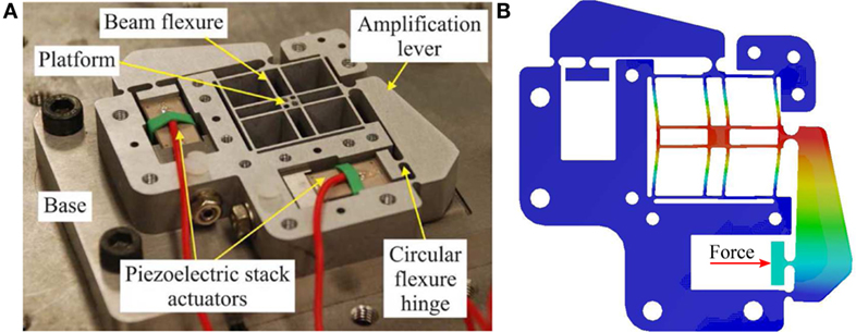
Figure 1. (A) Example of a flexure-guided XY nanopositioner (Yong et al., 2009). (B) Finite-element simulated motion of the nanopositioner, showing the deformation of flexures.
Piezoelectric stack actuators have been widely used in high-speed nanopositioning due to its ability to provide ultra-fast responses, fine movement, and high pushing force (Physik Instrumente, 2016). These actuators are constructed by bonding multiple layers of piezoelectric material together. There are bonded mechanically in series, and connected electrically in parallel as shown in Figure 2. All piezoelectric layers are poled in the direction of their thickness. The estimated total displacement of actuator is Δl = NVd33, where N is the number of piezoelectric layers, V is the driving voltage, and d33 is the piezoelectric coefficient. An inevitable drawback of piezoelectric stack actuators is that there are highly vulnerable to tensile and lateral forces (Fleming and Leang, 2014). When driving the actuator at high speeds, the high inertial (tensile) force due to the effective mass of nanopositioning system could damage the actuator (Chaplya et al., 2006; Koruza et al., 2015). A common practice to avoid such damage is to mechanically preload the piezoelectric stack to compensate for excessive tensile load. Flexures have been used to provide preload and guide the motion of piezoelectric stack actuators. For high-speed nanopositioning applications, stiff flexures are often used to achieve high mechanical bandwidth. Displacing these high-stiffness flexures in order to install and preload the piezoelectric stack actuator is a difficult task.
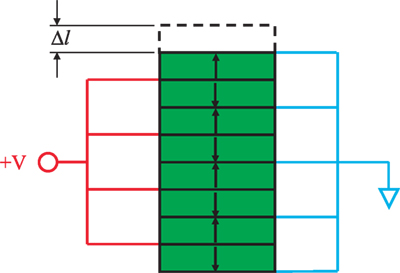
Figure 2. A piezoelectric stack actuator mechanically bonded in series, and electrically connected in parallel.
This paper surveys and discusses the challenges encountered in the design of high-speed, flexure-guided nanopositioning systems, with a special focus on preloading piezoelectric stack actuators using flexures. Section 2 discusses in details the advantages of preloading piezoelectric stack actuators. Some existing preload techniques for high-speed nanopositioning are discussed in Section 3. The yield strength limit of flexures during preloading piezoelectric stack actuators is analyzed and presented in Section 4. Section 5 presents a design example of a new preload mechanism for high-speed nanopositioning that tackles challenges discussed in this paper. Section 6 concludes the paper.
2. Preloading Piezoelectric Stack Actuator
Preloading piezoelectric stack actuators is important to protect them from tensile loads during high-speed operations. The application of preload has also found to improve the strain output of piezoelectric stack actuators (Mitrovic et al., 2001; Chaplya et al., 2006; Koruza et al., 2015). This enhanced performance is attributed to the increased number of available non-180° domains. As illustrated in Figure 3, the application of preload increases the number of domains perpendicular to the direction of the compressive stress, leading to an increased amount of non-180° domains available for switching when an electric field is applied (Lynch, 1996; Schaufele and Hardtl, 1996). However, the strain output reduces when the applied preload is above the peak stress value (Mitrovic et al., 2001; Koruza et al., 2015). The increase of preload also increases the hysteresis effect and potentially leads to excessive heat generation under long-term cyclic actuation that could degenerate the piezoelectric properties (Mitrovic et al., 2001).
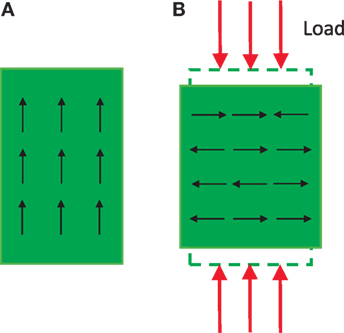
Figure 3. (A) Domains of a piezoelectric stack actuation before preload. (B) Increased amount of non-180° domains after the application of sufficient compressive load.
There are a few guidelines from the manufacturers in terms of the requisite preload for their piezoelectric stack actuators. Noliac (2015) recommends a minimum preload of 10 MPa for their piezoelectric stack actuators. They also suggests that the applied preload should not exceed 20% of the blocking force and the preload spring constant should be at most 10% stiffness of the piezoelectric stack actuator. Thorlabs Inc (2015) recommends to preload their discrete range piezoelectric stacks with 40% of their blocking forces in order to achieve the specified maximum displacements. The same company suggests to preload their co-fired piezoelectric stack actuators no more than 50% of their blocking forces. Physik Instrumente (2016) recommends that a preload of 15 MPa is sufficient to compensate for dynamic forces; and a preload of 30 MPa should not be exceeded. For high-speed nanopositioning designs, the preload value is often chosen to be about 10% stiffness of the piezoelectric stack actuator in order to achieve a high mechanical bandwidth design (Fleming and Leang, 2014).
3. Preload Techniques
There are several common preload techniques that include using (a) a pair of wedges (Handley et al., 2004; Lu et al., 2004; Cedrat Technologies, 2015; Wang and Zhang, 2015); (b) a preload block, screw, and nut (Chen and Dwang, 2000; Heverly et al., 2004; Yong et al., 2009; Yong and Moheimani, 2010; DeAngelis et al., 2015); (c) only flexures (Kenton and Leang, 2012; Wadikhaye et al., 2012; Yong et al., 2012, 2013; Fleming and Leang, 2014); and (d) permanent magnet (Baek et al., 2003). The first three techniques are illustrated in Figure 4. In method (a), one of the wedges is attached to the actuator. The other wedge is pushed down during installation to generate forward forces, which in turns preloads the actuator. The amount of preload can be easily estimated from the spring constant of the flexures and the slope of the wedges. However, the induced lateral forces during the installation procedure could potentially damage the piezoelectric stack actuator. In method (b), preload is applied by tightening the screw. This causes the steel ball to press against the preload block, and aligns the actuator with the direction of the applied force. This method is simple and it does not induce lateral forces to the actuator. However, the screw and preload block act as a mass-spring system with a lower resonance frequency than that of the actuator. This tends to limit the dynamic performance of nanopositioning systems.
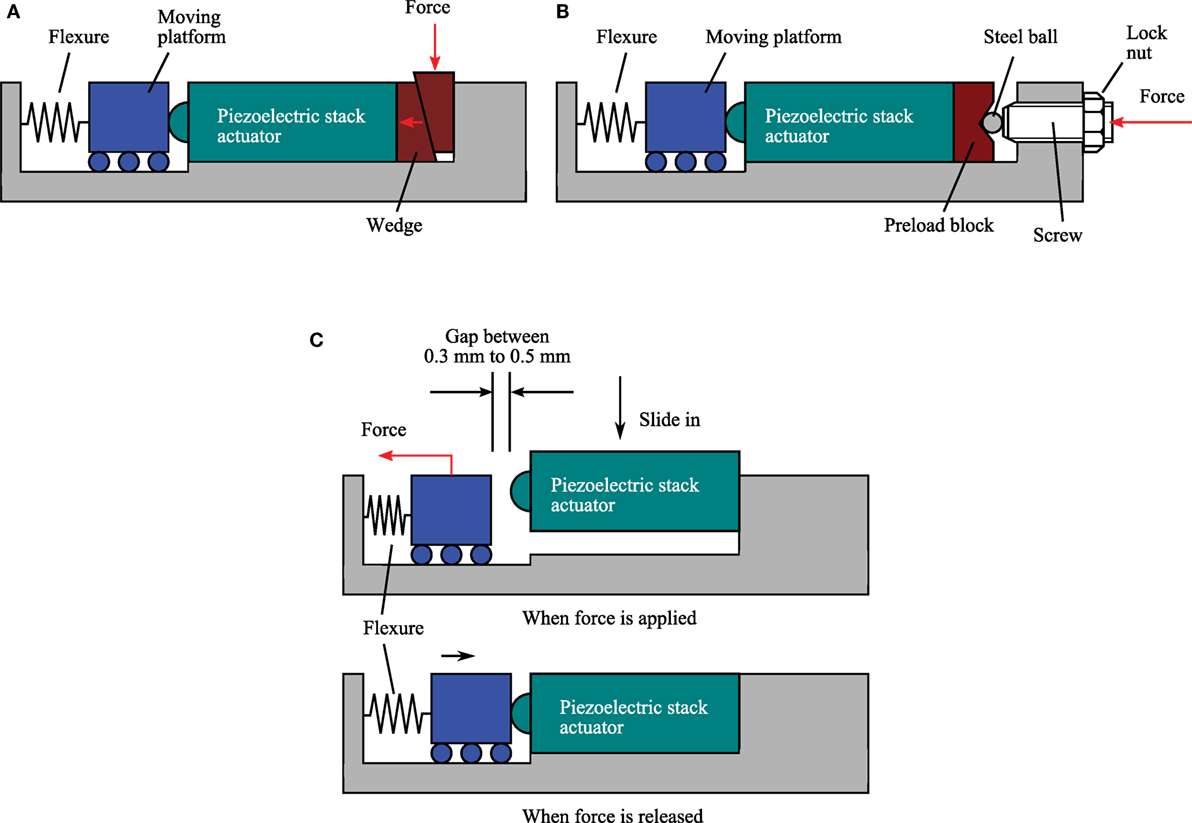
Figure 4. Common preload techniques used in piezoelectric stack actuated nanopositioning systems. (A) Using a pair of wedges. (B) Using precision screw and lock nut. (C) Using only flexures.
Many high-speed nanopositioning devices use only flexures to provide preload to the piezoelectric stack actuators as shown in Figure 4C. Typically, the flexures are elastically deformed by the applied forces to provide sufficient space for installing the actuator (Kenton and Leang, 2012; Yong, 2016). The piezoelectric stack actuator is then placed into the designated space. Forces are then released to return the flexures to its original position to clamp the actuator in place. This technique is simple without the need of additional components, such as wedges or preload screw that tends to introduce unwanted dynamics to the system. However, the installation process could be difficult especially for flexures with high stiffness. A practical gap of 0.3–0.5 mm is required to allow for sufficient space to slide the actuator in place without introducing excessive lateral forces to the actuator. For high-speed nanopositioning systems, flexures are designed to be about 10–20% of the actuator’s stiffness in order to achieve high mechanical bandwidth (Yong et al., 2012; Fleming and Leang, 2014). Some popular 10-mm long piezoelectric stack actuators used for high-speed nanopositioning stages are shown in Table 1. For a 5 mm × 5 mm × 10 mm actuator with a stiffness of 131.6 N/µm, the preferred total stiffness of flexures is 13.1 N/µm. To deform these flexures by 0.5 mm, a large applied force of about 6500 N is required. It is impractical to hang a 650 kg dead weight on the flexures to deform them. A carefully designed pulley system or a high-force preloading tool may be needed for this challenging task.
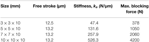
Table 1. Comparison of piezoelectric stack actuators from NOLIAC.
4. Yield Strength Limit of Flexure
The preload technique uses only flexures as illustrated in Figure 4C has been the popular choice to secure piezoelectric stack actuators for high-speed nanopositioning devices (Kenton and Leang, 2012; Wadikhaye et al., 2014; Yong et al., 2016). An issue that has often been neglected is the consideration of flexure’s yield strength limit especially during preloading piezoelectric stack actuators. During the installation and preloading process, the maximum yield stress experienced by the flexure should be kept below its yield strength limit. This is to ensure that the flexure deforms in its elastic region and continuously functions as a linear spring to provide the requisite preload to the actuator. The following provides a detailed analysis of yield strength limit of flexures during the preload process of actuators.
4.1. Estimation of Flexure’s Deformation and Stiffness
To find the maximum yield stress of flexure, the deformation and stiffness of flexure are first calculated. Figure 5 illustrates the displacements and loads acting on a flexure. Deformations at the free end can be derived using the Castigliano’s second theorem (Lobontiu, 2003) and arranged into matrix form as (Kenton and Leang, 2012; Yong et al., 2013)
where = and = . The torsional deformation θx is usually insignificant for nanopositioners discussed in this article. Therefore, θx is neglected in equation (1). For a basic beam flexure with constant thickness along its length L, the in-plane compliance equations are
where E is the Young’s modulus. Definitions of parameters L, h, and t can be found in Figure 5. The out-of-plane compliance equations are
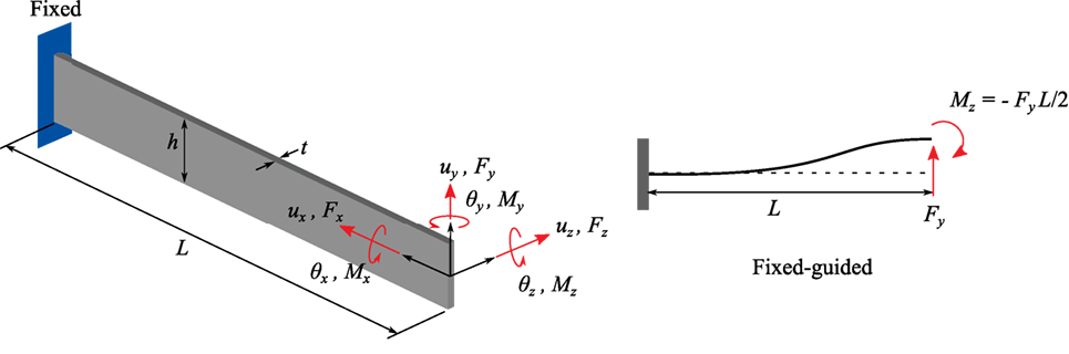
Figure 5. (Left) A flexure model with the applied loads and displacements at its free end. (Right) A flexure model with fixed-guided boundary condition.
For a relatively long beam compared to its height, the shearing effect can be ignored according to the Euler–Bernoulli beam model. This model assumes that the planar cross-section remains perpendicular to the neutral axis after the external bending has been applied. Shearing stresses and deformations are ignored. However, for a short beam, the shearing effect needs to be taken into consideration. With the shearing effect included, the in-plane compliance Cy−Fy and out-of-plane compliance Cz−Fz are
where G = E/[2(1 + v)], and v is the Poisson’s ratio. α is the shear correction factor, which is 6/5 for rectangular cross-section (Yong et al., 2013). For a fixed-guided boundary condition of a flexure with concentrated load (see Figure 5), the resultant moment at its guided end is Mz = − FyL/2. From equations (1) to (2), the deformation of the flexure along y-axis is
Therefore, the stiffness ky is
A nanopositioning design commonly constructed from connecting several flexures in parallel mechanically. Therefore, the effective stiffness is
where n is the number of flexures. Generally speaking, the effective stiffness keffy can be increased by increasing the number of flexures n, increasing the flexure thickness t, and decreasing the flexure length L. Large flexure height h is also one of the key factors for increasing keffy. However, it comes at an expense of a higher profile nanopositioner that increases the effective mass, thus reducing the mechanical resonance. This effect may not be attractive for high-speed nanopositioning systems. h is commonly chosen between 10 and 12.8 mm to reduce machining cost from a standard aluminum plate (Handley et al., 2004; Yong and Moheimani, 2010).
Many fabrication of high-speed nanopositioning stages use aluminum alloy Al7075 due to its relatively high yield strength, light weight, and high stiffness. Al7075 that has a Young’s modulus of 72 MPa and a yield strength of 505 MPa is considered here. As shown in equation (7), keffy is a cubic function with respect to ratio t/L. A slight increase in t/L will result in a large increment in keffy. This effect can be seen in Figure 6 where a contour map of keffy is plotted against t/L and n. Note that h is set to 10 mm in this plot.
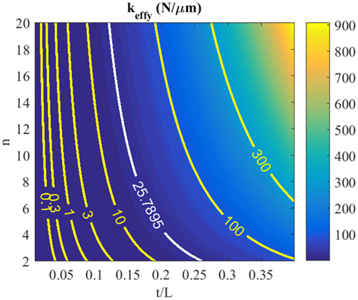
Figure 6. A contour map of effective stiffness keffy plotted against t/L and number of flexures n. The contour line plotted in white is the 10% stiffness of the 7 mm × 7 mm × 10 mm NOLIAC actuator as tabulated in Table 1.
4.2. Estimation of Yield Stress
According to the distortional energy density criterion (von-Mises) (Boresi and Schmidt, 2003),
where σf is the maximum yield stress of flexure, Mz is moment, Iy = ht3/12 is the second moment of inertia, c = t/2, Sy is the yield strength of the material, and SF is the safety factor. Mz = − FyL/2 and are substituted into equation (8), which is then simplified to,
It is noted that σf is independent to the flexure height h and number of flexure n. As mentioned in Section 3, a gap with practical distance is needed for the installation of the piezoelectric stack actuator, thus uy = 0.5 mm is chosen in equation (9) to calculate σf. The length L ∈ [1, 15] mm and thickness t ∈ [0.1, 0.5] mm are used to plot the maximum yield stress of the flexure in Figure 7. Considering a safety factor of 2, the threshold stress limit Sy/SF = 252.5 MPa is also plotted in the figure. For many high-speed nanopositioning designs, the effective stiffness of the stage is often chosen to be 10% of the piezoelectric stack actuator. Considering a 7 mm × 7 mm × 10 mm NOLIAC actuator that has a stiffness ka = 257.9 N/µm, its 10% stiffness is plotted in Figure 6. To achieve 10% of ka, the flexure dimension has to satisfy t/L ≥ 0.12 for n ≥ 2. However, Figure 7 shows that the t/L ratio has to be kept approximately within [0.01, 0.03] to satisfy equation (8), that is σf ≤ 252.5 MPa. The two t/L intervals do not coincide, implying that the two design criteria are trading off each other. In order to reduce stress, one needs to increase the length and reduce the thickness of the flexure. However, this will reduce the stiffness and, thus, the mechanical bandwidth of the nanopositioner. It is an impossible task to achieve a high-speed nanopositioning design with flexures that deform within their yield strength limit using existing preload techniques.
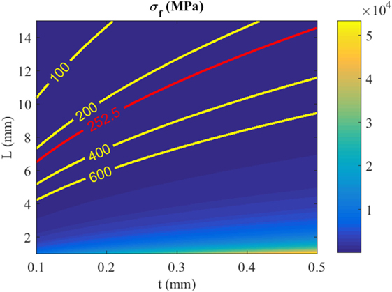
Figure 7. Maximum yield stress of flexure under deformation of 0.5 mm. The threshold stress limit is plotted in red.
5. Design Example: A New Preload Mechanism for High-Speed Nanopositioners
A novel preload mechanism that deals with challenges in high-speed nanopositioning systems is presented in this section. The design and functionality of the mechanism are briefly discussed here. Readers are referred to Yong (2016) for the detailed design, analysis, and experimental work.
The device is a vertical, one-axis nanopositioner that has a first resonance frequency along the actuation direction at 24 kHz, and a travel range of 10.6 µm. As shown in Figure 8, the nanopositioner consists of high-stiffness beam flexures to guide the motion of the central platform, and to provide the requisite mechanical bandwidth to the system. A preload mechanism which consists of two curved-beams are connected mechanically in parallel to the central platform. The other end of the curved-beams is connected to the base of the device. A piezoelectric stack actuator is located between the platform and fixed base. When a voltage is applied to the actuator, it displaces vertically, which in turns, elastically deforms the flexures to move the central platform vertically.
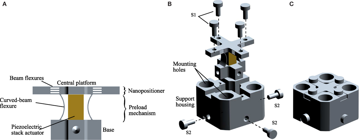
Figure 8. (A) A high-speed nanopositioning device with a novel preload mechanism design (Yong, 2016). (B,C) Exploded and assembled views of the device.
The curved-beams of the preload mechanism are designed to be much compliance than that of the beam-flexures. There are designed to satisfy the criteria in equation (8). There can be deformed by 0.35–0.5 mm with a force of 20 N or less using a simple setup as shown in Figure 9. During the installation of piezoelectric stack actuator, the central platform was fixed to a front jig. A fine pitch screw, which was held on a stationary back jig, was screwed onto the lock nut located at the base of the nanopositioner. When the screw was tightened, a pulling force was applied to the base and the curved-beams were deformed. The gap as shown in Figure 9 was kept to within 0.35–0.5 mm using a filler gage to ensure that the curved-beams were deformed within their elastic regions. The piezoelectric stack actuator was slided in between the curved-beams, followed by loosening the screw to clamp the actuator into position. After the piezoelectric stack actuator was installed, the nanopositioner was mounted to the support housing using four top screws (S1) and four bottom horizontal screws (S2) as shown in Figure 8.
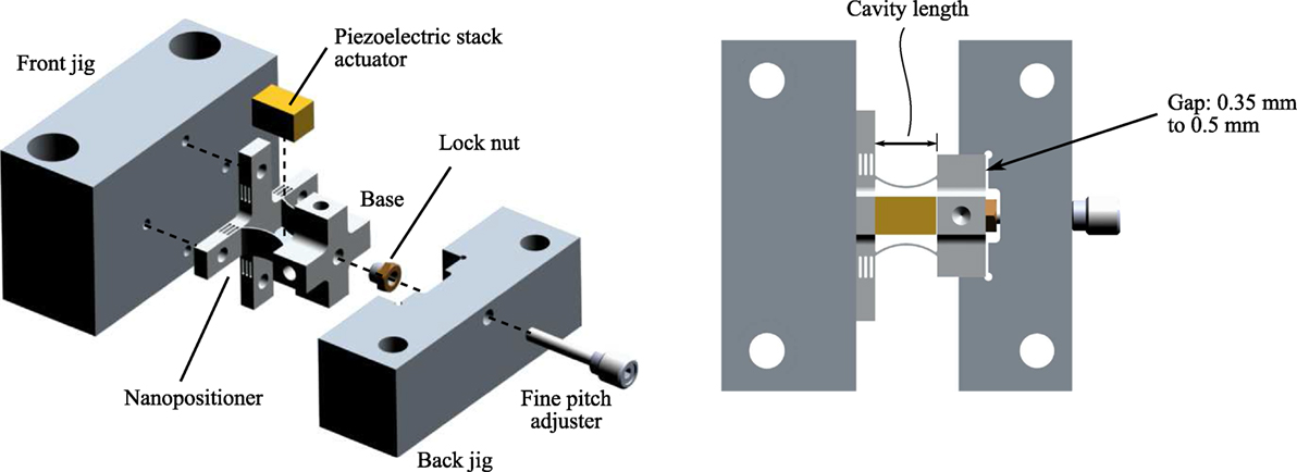
Figure 9. Experimental setup to preload and install the piezoelectric stack actuator.
After securing the nanopositioner to the support housing, the piezoelectric stack actuator is preloaded by the stiff beams as well as the curved flexures. Due to the fact that the piezoelectric stack actuator has a maximum displacement of only 10.6 µm, it will not deform the flexures beyond their elastic regions. The combined stiffness of the beam and curved flexures are 19.3 N/µm, which is ~10% stiffness of the piezoelectric stack actuator. This novel mechanism allows the ease of installation and preloading piezoelectric stack actuator while simultaneously achieves a high mechanical bandwidth design. Figures 10 and 11 show the experimental frequency response and displacement measurements of the device, showcasing the high-speed characteristic of the device with a first resonant peak at 24 kHz, and a large displacement range of 10.6 µm.
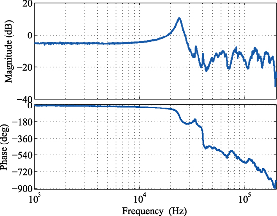
Figure 10. Measured frequency response of the nanopositioning stage (Yong, 2016).
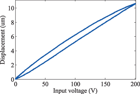
Figure 11. Measured displacement range of the nanopositioning stage (Yong, 2016).
6. Conclusion
This paper reviewed key challenges in mechanical design of high-speed flexure-guided nanopositioners with a special focus on issues related to preloading piezoelectric stack actuators. Piezoelectric stack actuators are highly intolerant to tensile forces. Preload is required to compensate for these forces especially during high-speed operations. Flexures are commonly used to preload piezoelectric stack actuators in high-speed nanopositioner designs. However, issues on flexure’s yield strength limit especially during preloading actuators are often overlooked. Analysis presented in this paper shows that using stiff flexures to preload piezoelectric stack actuator without deforming them beyond their elastic region is an impossible task. To tackle this issue, a novel preload mechanism design for high-speed nanopositioning is presented, which deals with the above challenges. This design allows the ease of installation and preloading piezoelectric stack actuators while simultaneously achieves a high mechanical bandwidth of 24 kHz and a large travel range of 10.6 µm.
Author Contributions
The author confirms being the sole contributor of this work and approved it for publication.
Conflict of Interest Statement
The author declares that the research was conducted in the absence of any commercial or financial relationships that could be construed as a potential conflict of interest.
Funding
This work was supported by the Australian Research Council DECRA Project (DE130100879).
References
Ando, T. (2012). High-speed atomic force microscopy coming of age. Nanotechnology 23, 062001. doi: 10.1088/0957-4484/23/6/062001
Baek, S., Han, C., Lee, C., and Noh, M. (2003). Design of a preload device for PZT actuator using permanent magnets. IEEE Trans. Magn. 39, 2965–2967. doi:10.1109/TMAG.2003.816708
Berden, G., Peeters, R., and Meijer, G. (2000). Cavity ring-down spectroscopy: experimental schemes and applications. Int. Rev. Phys. Chem. 19, 565–607. doi:10.1080/014423500750040627
Boresi, A. P., and Schmidt, R. J. (2003). Advanced Mechanics of Materials, 6th Edn. John Wiley & Sons, Inc.
Cedrat Technologies. (2015). Cedrat Technologies. Available at: http://www.cedrat-technologies.com/ for their nanopositioning systems
Chaplya, P. M., Mitrovic, M., Carman, G. P., and Straub, F. K. (2006). Durability properties of piezoelectric stack actuators under combined electromechanical loading. J. Appl. Phys. 100, 124111. doi:10.1063/1.2407269
Chen, J. S., and Dwang, I. C. (2000). A ballscrew drive mechanism with piezo-electric nut for preload and motion control. Int. J. Mach. Tools Manuf. 40, 513–526. doi:10.1016/S0890-6955(99)00078-4
DeAngelis, D. A., Schulze, G. W., and Wong, K. S. (2015). Optimizing piezoelectric stack preload bolts in ultrasonic transducers. Phys. Proc. 63, 11–20. doi:10.1016/j.phpro.2015.03.003
Debecker, I., Mohamed, A., and Romanini, D. (2005). High-speed cavity ringdown spectroscopy with increased spectral resolution by simultaneous laser and cavity tuning. Opt. Express 13, 2906–2915. doi:10.1364/OPEX.13.002906
Fleming, A. J., and Leang, K. K. (2014). Design, Modeling and Control of Nanopositioning Systems. London, UK: Springer.
Gorman, J. J., Dagalakis, N. G., and Boone, B. G. (2003). “Multi-loop control of nanopositioning mechanism for ultra-precision beam steering,” in Proceedings of SPIE Conference on Free-Space Laser Communication and Active Laser Illumination III, Vol. 5160 (San Diego, CA), 170–181.
Handley, D., Lu, T.-F., Yong, Y., and Zhang, W. (2004). “A simple and efficient dynamic modelling method for compliant micropositioning mechanisms using flexure hinges,” in Proceedings of SPIE on Device and Process Technologies for MEMS, Microelectronics, and Photonics III (Perth: SPIE), Vol. 5276, 67–76.
Heverly, D. E., Wang, K. W., and Smith, E. C. (2004). Dual-stack piezoelectric device with bidirectional actuation and improved performance. J. Intell. Mater. Syst. Struct. 15, 565–574. doi:10.1177/1045389X04044450
Kenton, B. J., and Leang, K. K. (2012). Design and control of a three-axis serial-kinematic high-bandwidth nanopositioner. IEEE/ASME Trans. Mechatron. 17, 356–368. doi:10.1109/TMECH.2011.2105499
Koruza, J., Franzbach, D. J., Schader, F., Rojas, V., and Webber, K. G. (2015). Enhancing the operational range of piezoelectric actuators by uniaxial compressive preloading. J. Phys. D Appl. Phys. 48, 215302. doi:10.1088/0022-3727/48/21/215302
Liu, Y., and Xu, Q. (2016). Mechanical design, analysis and testing of a large- range compliant microgripper. Mech. Sci. 7, 119–126. doi:10.5194/ms-7-119-2016
Lobontiu, N. (2015). Modeling and design of planar parallel-connection flexible hinges for in- and out-of-plane mechanism applications. Precis. Eng. 42, 113–132. doi:10.1016/j.precisioneng.2015.04.007
Lobontiu, N., and Garcia, E. (2003). Two-axis flexure hinges with axially-collocated and symmetric notches. Comput. Struct. 81, 1329–1341. doi:10.1016/S0045-7949(03)00056-7
Lobontiu, N., Paine, J. S. N., Garcia, E., and Goldfarb, M. (2001). Corner-filleted flexure hinges. Trans. ASME J. Mech. Design 123, 346–352. doi:10.1115/1.1372190
Lu, T.-F., Handley, D. C., Yong, Y. K., and Eales, C. (2004). A three-DOF compliant micromotion stage with flexure hinges. Ind. Robot 31, 355–361. doi:10.1108/01439910410541873
Lynch, C. S. (1996). The effect of uniaxial stress on the electro-mechanical response of 8/65/35 PLZT. Acta Mater. 44, 4137–4148. doi:10.1016/S1359-6454(96)00062-6
Mitrovic, M., Carman, G. P., and Straub, F. (2001). Response of piezoelectric stack actuators under combined electro-mechanical loading. Int. J. Solids Struct. 38, 4357–4374. doi:10.1016/S0020-7683(00)00273-0
Miyahara, K., Nagashima, N., Ohmura, T., and Matsuoka, S. (1999). Evaluation of mechanical properties in nanometer scale using AFM-based nanoindentation tester. Nanostruct. Mater. 12, 1049–1052. The Fourth International Conference on Nanostructured Materials (NANO ’98). doi:10.1016/S0965-9773(99)00297-4
Noliac. (2015). Noliac. Available at: http://www.noliac.com/ for specifications of their piezoelectric stack actuators
Noveanu, S., Lobontiu, N., Lazaro, J., and Mandru, D. (2015). Substructure compliance matrix model of planar branched flexure-hinge mechanisms: design, testing and characterization of a gripper. Mech. Mach. Theory 91, 1–20. doi:10.1016/j.mechmachtheory.2015.04.001
Physik Instrumente. (2016). The World of Micro- and NanoPositioning (PI Catalog). Karlsruhe, Germany: Physik Instrumente.
Schaufele, A. B., and Hardtl, K. H. (1996). Ferroelastic properties of lead zirconate titanate ceramics. J. Am. Ceram. Soc. 79, 2637–2640. doi:10.1111/j.1151-2916.1996.tb09027.x
Schitter, G., Astrom, K. J., DeMartini, B., Thurner, P. J., Turner, K. L., and Hansma, P. K. (2007). Design and modeling of a high-speed AFM- scanner. IEEE Trans. Control Syst. Technol. 15, 906–915. doi:10.1109/TCST.2007.902953
Thorlabs Inc. (2015). Thrlabs Inc. Available at: http://www.thorlabs.com/ for specifications of their piezoelectric stack actuators
Vicary, J. A., and Miles, M. J. (2009). Real-time nanofabrication with high-speed atomic force microscopy. Nanotechnology 20, 095302. doi:10.1088/0957-4484/20/9/095302
Wadikhaye, S., Yong, Y. K., and Moheimani, S. O. R. (2012). Design of a compact serial-kinematic scanner for high-speed atomic force micros- copy: an analytical approach. Micro Nano Lett. 7, 309–313. doi:10.1049/mnl.2011.0477
Wadikhaye, S., Yong, Y. K., and Moheimani, S. O. R. (2014). A serial-kinematic nanopositioner for high-speed AFM. Rev. Sci. Instrum. 85, 105104(10). doi:10.1063/1.4897483
Wang, R., and Zhang, X. (2015). Preload characteristics identification of the piezoelectric-actuated 1-DOF compliant nanopositioning platform. Front. Mech. Eng. 10:20–36. doi:10.1007/s11465-015-0328-z
Wang, Z., Chen, L., and Sun, L. (2007). “An integrated parallel micromanipulator with flexure hinges for optical fiber alignment,” in IEEE International Conference on Mechatronics and Automation (Harbin), 2530–2534.
Wiesauer, K., and Springholz, G. (2000). Fabrication of semiconductor nanostructures by nanoindentation of photoresist layers using atomic force microscopy. J. Appl. Phys. 88, 7289–7297. doi:10.1063/1.1324693
Xu, Q. (2015). Robust impedance control of a compliant microgripper for high-speed position/force regulation. IEEE Trans. Ind. Electron. 62, 1201–1209. doi:10.1109/TIE.2014.2352605
Yong, Y. K. (2016). A new preload mechanism for a high-speed piezoelectric stack nanopositioner. Mechatronics 36, 159–166. doi:10.1016/j.mechatronics.2016.03.004
Yong, Y. K., Aphale, S., and Moheimani, S. O. R. (2009). Design, identification and control of a flexure-based XY stage for fast nanoscale positioning. IEEE Trans. Nanotechnol. 8, 46–54. doi:10.1109/TNANO.2008.2005829
Yong, Y. K., Bhikkaji, B., and Moheimani, S. O. R. (2013). Design, modeling and FPAA-based control of a high-speed atomic force microscope nanopositioner. IEEE/ASME Trans. Mechatron. 18, 1060–1071. doi:10.1109/TMECH.2012.2194161
Yong, Y. K., and Fleming, A. J. (2016). High-speed vertical positioning stage with integrated dual-sensor arrangement. Sens. Actuators A Phys. 248, 184–192. doi:10.1016/j.sna.2016.06.042
Yong, Y. K., Lu, T.-F., and Handley, D. C. (2008). Review of circular flexure hinge design equations and derivation of empirical formulations. Precis. Eng. 32, 63–70. doi:10.1016/j.precisioneng.2007.05.002
Yong, Y. K., and Moheimani, S. O. R. (2010). “A compact XYZ scanner for fast atomic force microscopy in constant force contact mode,” in IEEE/ASME International Conference on Advanced Intelligent Mechatronics (Montreal, QC), 225–230.
Yong, Y. K., and Moheimani, S. O. R. (2015). Collocated z-axis control of a high-speed nanopositioner for video-rate atomic force microscopy. IEEE Trans. Nanotechnol. 14, 338–345. doi:10.1109/TNANO.2015.2394327
Yong, Y. K., Moheimani, S. O. R., Kenton, B. J., and Leang, K. K. (2012). Invited review article: high-speed flexure-guided nanopositioning: mechanical design and control issues. Rev. Sci. Instrum. 83, 121101. doi:10.1063/1.4765048
Keywords: preload, piezoelectric stack actuator, flexure, nanopositioning, high speed
Citation: Yong YK (2016) Preloading Piezoelectric Stack Actuators in High-Speed Nanopositioning Systems. Front. Mech. Eng. 2:8. doi: 10.3389/fmech.2016.00008
Received: 11 August 2016; Accepted: 07 October 2016;
Published: 27 October 2016
Edited by:
Thrishantha Nanayakkara, King’s College London, UKCopyright: © 2016 Yong. This is an open-access article distributed under the terms of the Creative Commons Attribution License (CC BY). The use, distribution or reproduction in other forums is permitted, provided the original author(s) or licensor are credited and that the original publication in this journal is cited, in accordance with accepted academic practice. No use, distribution or reproduction is permitted which does not comply with these terms.
*Correspondence: Yuen Kuan Yong, yuenkuan.yong@newcastle.edu.au