
 Here is a circuit for a simple but useful low-cost quadraphonic (having four channels) amplifier. It can be used for experiments in open or closed spaces, including small home labs and studios. It can also be used for the creation of audio effects and as a small audio-distribution amplifier.
Such an amplifier can be used in mono-, stereo-, quadro-phony, or for audio effects, mixing audio signals, or as small public announcement systems, small audio distribution systems, low-power amplifiers for electrical instruments, noise distribution systems, audio line drivers, bridged and paralleled audio amplifiers, and so on.
For these and similar purposes, we need a multi-channel audio amplifier. In many cases the required power per channel is in the range 0.3W to 1W. Also, preferably, the audio amplifier should be capable of working on a battery, car accumulator or simple 1A to 2A wall adaptor.
To keep this quadraphonic amplifier using LM386 simple and inexpensive, it does not have tone-control potmeters.

Circuit and working
Circuit diagram of the quadraphonic amplifier is shown in Fig. 1. Circuits of all its four channels are identical. These have separate inputs (CON1, CON2, CON3 and CON4) and separate outputs (CON5, CON6, CON7 and CON8), which can be used for different purposes. Also, the amplifiers can be used in bridge or in parallel mode with appropriate input signals.
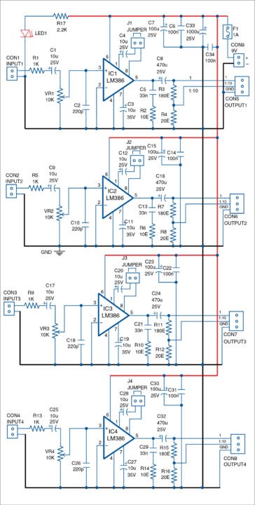
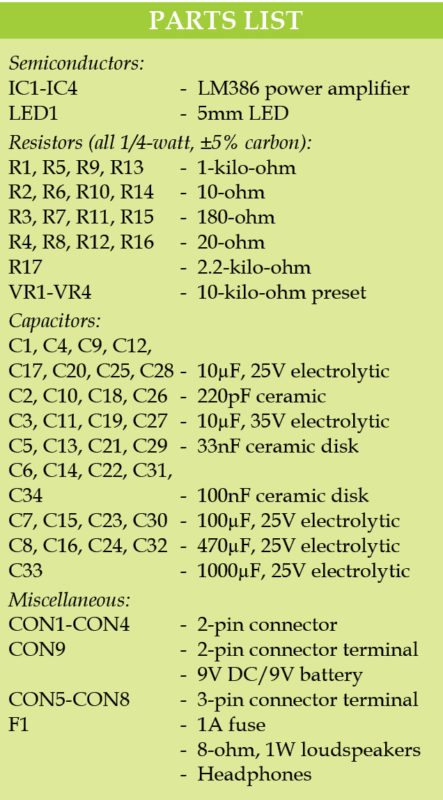
Inputs of the four amplifiers have separate volume-control potmeters VR1, VR2, VR3 and VR4, respectively. Input capacitors C1, C9, C17 and C25 should be preferably not polarised, which makes the circuit independent of the polarity of the DC component of input signals. Capacitors C2, C10, C18 and C26 reduce the sensitivity of amplifiers to high-frequency RFI and EMI captured by the inputs.
Capacitors C3, C11, C19 and C27 reduce the sensitivity of amplifiers to noise from the power supply. The external power supply connected to CON9 is common for all four channels. The circuit has common fuse F1 and common large filtering capacitor C33=1000µF/25V. A well-regulated, low-noise external power supply should be used.

The circuit is built around the popular low-voltage audio-power amplifier LM386. LM386, AZ386, JRC386, NJM386 and similar integrated circuits (ICs) are easily available in the market. These are low-cost and suitable for many audio and control applications.
LM386 is produced by National Semiconductor Corp. in several versions with different power supply voltage ranges. Here, ICs in dual-in-line (DIP or DIL) packages are used.
It is important to respect the power dissipation of LM386. In all cases, it is recommended not to go above 80 percent of the values in the datasheet. This is because everything cannot be taken into consideration at the design stage, and the IC should not operate for a long time at its maximum power dissipation.
LM386N-1 and LM386N-3 have an operating supply range of four volts to 12 volts (maximum 15 volts) and LM386N-4 has an operating supply range of five volts to 18 volts (maximum 22 volts).
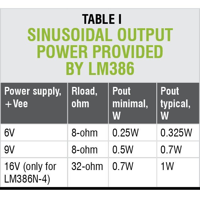
Maximum power dissipation of DIP/DIL at +25°C is 1.25W. Table I gives the guaranteed level of the sinusoidal output power (Pout) provided by LM386.
In the datasheet, power dissipation of LM386 is guaranteed on loads of 4-ohm, 8-ohm and 16-ohm. But most parameters of the ICs are given only for a load of 8-ohm.
Generally speaking, if we accept the maximum power dissipation around 1.25W, we have the following approximate limitations:
- With a load of 16-ohm, power supply could go up to 14V, or even 16V (more than 15V only for model LM386N-4)
- With a load of 8-ohm to 12-ohm, up to 12V to 15V
- With a load of 4-ohm, up to 9V, or even 12V
- With a load of 2-ohm, up to 5V, or even 6V
Load of 2-ohm is not mentioned in the data sheet. So the risk of using it would be entirely upon by the user. LM386N-1 could work off +5V power supply from a USB port, if needed.
It is advised to use large copper paths on the PCB to relieve the heat from the IC. Most frequently the IC is not loaded continuously to the maximum. But for musicians practicing heavy distortions, LM386 could be overloaded. Measures should be taken not to overheat the IC. Luckily, it is not easy to damage the IC by overloading.
Gain of LM386 could be set from 20 to 200. When jumpers J1, J2, J3 and J4 are open, gain of the corresponding amplifier is 20. If these jumpers are closed, gain of the corresponding IC is 200. LM386 has internal individual input resistors of around 50-kilo-ohm between inputs 2 and 3 and ground pin 4.
Each amplifier has two types of outputs. Main outputs are for loudspeakers. The loudspeakers should have impedance of at least 8-ohm and power rating of 2W, and mounted in a wooden box. Outputs with resistive dividers (1:10) are for headphones.
Connecting low-impedance headphones, for example, with 32-ohm or less, will not damage the outputs.
Construction and testing
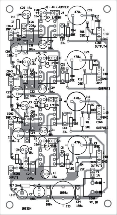
A single-side PCB pattern of the low-cost quadraphonic amplifier is shown in Fig. 2 and its component layout in Fig. 3.
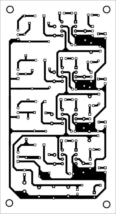
Download PCB and component layout PDFs: click here
The full power supply range of LM386 is available. The preferred power supply is stabilised with regulators such as 7805, 7806, 7808, 7809, 7812 and 7815, depending on the selected load resistances.
The circuit could work with low-cost wall adaptors that provide necessary voltage and at least 1A output average current. All filtering capacitors should not be omitted, even if there are such capacitors in the external power supply.
LM386 can work successfully off a 6V battery from a motorcycle or kids’ electric car (typically 6.6V, maximum around 7.7V). The audio amplifier could work with one, two or three 4.5V batteries of type 3R12. Working with a single battery of 9V such as 9F22 is possible but not for a long time.
The amplifier gives output power up to around 1W per channel and has a wide range of applications.
Petre Tzv Petrov was a researcher and assistant professor in Technical University of Sofia (Bulgaria) and expert-lecturer in OFPPT(Casablance), Kingdom of Morocco. Now he is working as an electronics engineer in the private sector in Bulgaria.


How to bridge two lm386 ICs ?
1. How to reduce Clipping of audio when volume is increased ?
2. How to Bridge two Lm386 ics ?