Paralleling DC-DC Converters: 5 Things You Need to Know
03-09-2015 | By Philip Lechner
Philip Lechner's career in electronics distribution has spanned 33 years, including 13 years as a field sales engineer covering power, semiconductors and IP&E, and 20 years in product management for power supplies and DC/DC converters for Avnet Abacus.
In the world of electronics distribution, there are many situations where a high load current is required that a single DC-DC converter cannot provide. In these cases, connecting two or more DC-DC converters in parallel can effectively double the current available to the load. However, it's important to ensure that load current is shared equally between the converters to optimise their lifetime and prevent thermal hot spots. There are various load-sharing techniques available, including current sensing and droop methods. Additionally, synchronising switching frequencies can reduce ripple and interference. When selecting DC-DC converter modules for parallel operation, it's essential to check whether they are designed for this purpose and have load-sharing schemes implemented. This article provides an overview of the reasons for paralleling DC-DC converters, load-sharing techniques, and factors to consider when selecting modules for parallel operation.
1.) There are lots of good reasons to parallel
Many situations demand high load current that is more than a single DC-DC converter can provide. In these cases, two or more DC-DC converters may be connected in parallel to meet this current requirement. When using a DC-DC converter parallel connection, the current available to the load may be effectively doubled.
Why not just use a really big DC-DC? Well, bigger converters can be less efficient than their smaller counterparts, for a start. Bigger passives will be required, which take up space. Designing such power systems is not straightforward either – sometimes paralleling is the more accessible, quicker option. Also, using two smaller DC-DCs instead of one big one will spread the heat dissipated across a larger area on the PCB, helping reliability.
Other reasons for using DC-DC converters in parallel include providing redundancy in high-reliability systems. These setups use additional DC-DC converters; that is, there are always more converters available than is required to provide the total load current – if one fails, the same amount of current can still be provided. Popular schemes are N+1 (where there is one redundant converter), N+M or even 2N for high levels of redundancy.
2.) Load current should be shared equally
Two DC-DC converters connected in parallel will not automatically share the load equally. Even if they are apparently identical, the output voltages will be slightly different due to component tolerances. The DC-DC converter with the higher output voltage will typically provide the entire load current, operating at its limit while its partner is doing relatively little work. This will provide the required amount of power, but it’s hardly optimal.
The converter doing the bigger share of the work will create a thermal hot spot, which could be problematic, and it will have a shorter expected lifetime under these conditions. Forcing DC-DC converters to share the load equally mitigates hot spots and optimises the lifetime for all the modules.
For parallel DC-DC converters operating in redundant configurations, if one module fails, the others must increase their output to compensate. If the modules are loaded unequally and the one providing most of the current fails, its partner must quickly increase its load from minimal to the maximum to compensate, which causes undesirable transients and a temporary drop in the output. Sharing the load equally minimises the dynamic response required from each converter, resulting in less output disruption.
3.) There are lots of different ways of implementing load sharing
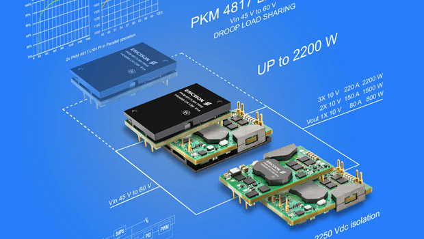
There are several commonly used techniques for load sharing in parallel DC-DC systems. One of the most common techniques senses the output current from each converter and compares it to the average, using current sense resistors, sensing amplifiers and a summing amplifier. The converters’ outputs are adjusted using trim or sense pins when necessary. Another popular method, the droop-share method, reduces the output voltage as a function of load current if one converter produces more current than another. Power supplies such as Murata’s DBQ series and Ericsson’s PKM4817LNH module use the droop method to allow them to be operated in parallel.
A master/slave setup may be implemented using one intelligent module as the master, which controls the outputs of the other DC-DC converters. Other techniques, such as analogue current sharing, use only intelligent modules and actively adjust the output voltage of each supply.
4.) Synchronising switching frequencies reduces ripple
There will always be some discrepancies between switching frequencies in the converters used, even when operating identical parts from the same input bus. Even slight mismatches in switching frequencies can result in unwanted beat frequencies; that is, the switching frequencies can interfere with each other. The resulting frequencies can create ripple currents at the converters’ input. These ripple currents cause losses in the interconnects between the converters and can place additional stress on input bypass capacitors. In extreme situations, ripple currents can falsely trigger overcurrent conditions.
DC-DC converters that have the ability to be synchronised may be selected to avoid this problem. Alternatively, beat frequencies and the resulting ripple currents can be suppressed using filters.
5.) Never assume modules can be paralleled
When selecting DC-DC converter modules for an application in which they will be paralleled, it’s essential to check carefully to ensure that the modules you are looking at are designed for operation in parallel. Not all modern DC-DC converters have this capability; those with fixed outputs and no feedback terminals are unlikely candidates. Those that do allow parallel operation will have some kind of load-sharing scheme implemented (such as the droop-share method described above). This should be stated in the manufacturer’s data sheets, or contact Avnet Abacus for advice.