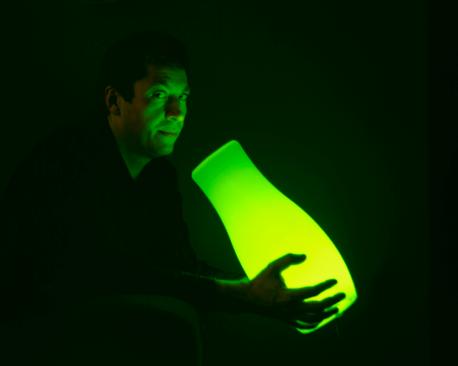
Seeing great potential in a normal, off-the-shelf product, Pete Griffiths designed a circuit he popped into the lamp to give it a new lease of life. His design combines a PIC and three constant current buck converters to create the RGB LED controller. This controller drives the high power 350mA LEDs using PWM to control the LED brightness. By driving the red, green and blue LEDs with varying pulse widths the controller can generate up to 16 million colours using fades, strobe and static effects. Who says you can’t give the humble lamp a nip and tuck?
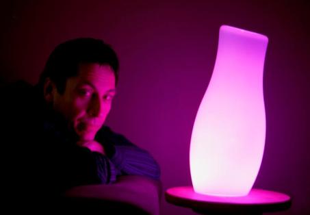
The main reason I made this version is that I wanted to fit it in to the base of an Ikea Mylonit lamp. This lamp is made entirely from glass and has a small recess in the base with an entry for the power lead.
Since it had nowhere to fit a separate power connector but did have a slot for a power lead to pass in to the base, I needed to make a PCB with a DC power connector in the centre of the board. At the same time I took the opportunity to tweak the circuit slightly and left out things it didn’t need. The changes are detailed below. Please note that the original version on the main page is still perfectly okay and you may find the single sided PCB easier to make.
Construction

You must drill vias and solder links between the ground plane and the top side of the board.
There are also six vias linking tracks on the top and bottom of the PCB. You must ensure you add these or the circuit will not function correctly, if at all.
The pad size for the three inductors is SM2512. There are such a variety of inductors that could be used here with so many different footprints. I’ve left some clear area around the pads to facilitate the use of various inductors but you should make sure that the ones you do use aren’t going to touch other areas of copper. This may require some creative positioning of the inductors.
The RGB LEDs connect with the anode to the inductor and the cathode to the track that disappears under the ZXLD1350’s. This should be apparent from the schematic but I’ll mention it anyway.
The 5 pin ICSP header needs soldering on the component side of the PCB and the middle pin also needs soldering on the copper side. It can be fitted to either side of the board depending on how you are going to mount the PCB, but you must make sure you solder it so it connects all the PCB tracks. This probably makes more sense if you look at the PCB.
The push button switch can be mounted on either side of the PCB to suit your specific application.
The LED is fixed to the aluminium disc using Adhesive Thermal Pads.
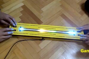
In the photographs below, the PCB is fixed to the aluminium disc using thick (foam backed) double sided tape. The tape is doubled up to give some clearance between the disc and underside of the PCB and a thin sheet of plastic (from take-away food container) is used to provide insulation between the two.
The depth of the recess in the base of the lamp requires that you make the whole assembly as shallow as possible, otherwise the body of the DC power connecter will be below the bottom of the lamp base. Keep this in mind when assembling it.
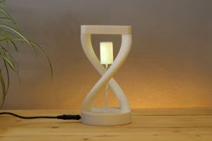
A ping pong ball, cut in two makes a good light diffuser. I’ve also used opaque tops from aerosol tins to good effect.
Although this specific application makes use of a single package RGB LED, it is equally suited to driving separate red, green and blue LEDs. It can also drive 3 pairs of series connected LEDs. However, it cannot be used with RGB LEDs that have a common anode or cathode.
Worth checking out are the Lamina Atlas RGB LEDs which contain 3 pairs of series connected LED dies in one package. These are very bright, just remember to use a heatsink capable of dealing with 6.6W heat dissipation. It works well with the controller described here but the aluminium disc shown with this project can’t handle the heat so if you’re thinking of using one you’ll need to do some redesign work.
Warning: Do not look directly into high brightness LEDs; they can damage your eyes.
Software
Source code available from High Brightness LED driver page.
The colour sequences included are a minimal set for testing. They are:
1. Constant red 100%
2. Constant green 100%
3. Constant blue 100%
4. All off
5. White 5%
6. White 50%
7. White 70%
8. Red fade up/down; Green fade up/down; Blue fade up/down
9. Red fade up/blue fade down; Green fade up/red fade down; Blue fade up/ green fade down
10. Blue 5% blinking
Sequence data information
Since the supplied SequenceData350.inc file contains only basic sequences for testing you will want to modify the SequenceData350.inc file with your own sequences and reassemble the code.
The format for this file is exactly the same as that used with the other RGB controllers on this site. For an explanation of the sequence data format see Standalone RGB controller SequenceData.inc file.
| Quantity | RS Part # | Part description |
| 1 | 544-1686 | 8 bit microcontroller, PIC12F629-I/SN |
| 1 | 516-6149 | MC78L05ACDG |
| 1 | 155-169 | Diode, Schottky, low leakage 1A, ZLLS1000TA |
| 1 | 648-0733 | 1206 X7R ceramic capacitor, 16V 1uF |
| 1 | 648-0957 | 0805 X7R ceramic capacitor, 16V 0.1uF |
| 1 | 223-0499 | CRG0805 SMT chip resistor, 3K3 0.125W |
| 1 | 223-0607 | CRG0805 SMT chip resistor, 22K 0.125W |
| 1 | 223-0641 | CRG0805 SMT chip resistor, 47K 0.125W |
| 1 | 445-2039 | NPN transistor, BC848C 0.1A Ic 5Vce |
| 1 | 436-7818 | Schottky barrier diode,BAT54 0.2A 30V |
| 1 | 479-1407 | 6x6mm tactile switch, 4.3mm H 2.6N |
| 1 | 540-9424 | Choke Coil SMD, 68uH, 500 mA, ELL6SH680M |
| 1 | 477-4878 | Bond-ply 100 2sided adhesive tape,1x2in |


It looks great 🙂
HI
I read your article on the PWM RGB LED
Lamina Atlas LEDs. I would like to apply this in an application where the LEDs are controlled through a serial port. Can you tell me if you sell this assembled and ready for use? What computer language operates the PWM contoller to change colors?
Please advise.
Sincerely
Mario
Top 10 most popular articles on ElectronicsWeekly.com
Here are the top ten most popular articles on ElectronicsWeekly.com in the last week, with Gadget Freak in cruise control with a number of car-related electronic devices. From the News Index, Nokia and Qualcomm getting together to sort out their epic 3…
links for 2008-02-14
David Manners highlights predictions of chaos in the semiconductor industry (tags: davidmanners IFS2008 semiconductors futurehorizons) Making art from lamps (tags: art lamps gadgetfreak LED)…