Peter Griffiths – the man who made a lamp into a work of art and turned to LEDs for F1 gantry start-lights – returns with some LED chasing. This neat little circuit provides 8 LEDs directly driven from the PIC along with a single mode control switch. The firmware described drives the LEDs with a 5 bit PWM signal providing each of the 8 LED channels with four levels of intensity; off, dim, mid, bright. A number of sequences are programmed into the firmware to provide some interesting visual effects and chase sequences, including the classic effect seen on the car in the Knight Rider TV series. Peter says that the design is deliberately simple with each LED being directly driven from a PIC I/O pin. This and the inclusion of an in-circuit programming header (ICSP) make the circuit ideal for teaching/learning introductory PIC assembly language programming. However, he writes, if you just want a cool LED chaser without having to write any code, a ready written LED chaser program with fully commented source code and programmer ready HEX files is provided at the bottom of this page. The circuit has been constructed on a PCB but can easily be built on strip-board, or a solderless breadboard. 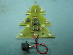 Possible apps include an Xmas Tree Chaser and, bending the LEDs through 90°, you have a UFO chaser. Fully documented in terms of parts and the build process, Peter has photos, circuit descriptions and lots of data to help navigate construction. Circuit Description Download a PDF of the schematic. The heart of the LED chaser is the PIC 16F628A microcontroller, IC2. The program that runs on this chip controls the LEDs attached to the output port pins. Resistors R1 thru R8 limit the current through LED1 – LED8 to a safe level that won’t damage the PICs I/O ports or LEDs. Resistor R9 provides a pull-up for the input connected to switch S1. R10 pulls up the PIC’s MCLR reset signal during normal operation while allowing the input to be raised to 12.5 volts during in-circuit programming. JP1 provides connection for an ICSP programmer such as a PICkit2 making it easy to reprogram the PIC without removing it from the PCB. Firmware The program has three modes of operation.
- Manual mode will run the same sequence continually. When the switch is pressed it will skip to the next sequence in program memory.
- In auto-sequential mode, the program runs through each sequence in program memory until it reaches the end of all defined sequences at which point it restarts from the first one.
- In random mode the program selects sequences randomly.
You can read more about the Firmware operation. Note: The PIC 16F628A microcontroller requires programming with the firmware which you can download. Read about the Firmware Download. Supported PICs The PIC 16F628A is a newer revision of the 16F628. As far as the circuit and firmware are concerned the two are functionally identical and you can use either part. 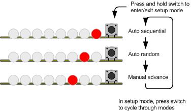 The PIC 16F84A can also be used with the firmware mentioned. You will however need to make changes to the hardware design and PCB layout to include an external 4Mhz crystal and load capacitors or a ceramic resonator, since the 16F84A doesn’t have the internal oscillator of the 16F628A. You will also need to remove the last sequence from the pwmc_SeqDat.inc file before assembling the code otherwise it won’t fit in the 1K program memory of the 16F84A. Parts List You can read Peter’s extensive documentation of the project on his website, including a fully-detailed parts list.