By Mike Collins, Federal Manufacturing
Thorough cleaning and sanitizing of equipment for processing and packaging dairy products is absolutely necessary for providing the highest level of food safety, product quality, and establishing and maintaining consumer trust. Proper sanitation also has a profound effect on lowering waste and improving output, both of which contribute to a healthy bottom line.
This white paper details the history of sanitizing dairy filling machines and describes what to watch for in terms of state-of-the-art systems and what processes to avoid.
The old way of cleaning, sanitizing dairy processing equipment
Before today’s automated clean in place (CIP) systems, dairy packaging equipment was commonly dissembled, cleaned with a brush and a pail of soapy water, and left to air dry. These machines were then reassembled and sanitized just prior to production. This method was not only laborious, but often ineffective as the equipment was easily contaminated during reassembly.
Considering the shortcomings of manual cleaning, it didn’t take long for filling machine manufacturers to take the first steps toward an automated solution. This was the start of CIP. The CIP cleaning method required tanks for rinse water and cleaning solutions, pumps, and piping circuits in order to complete a CIP loop. It was important to circulate solutions through the product contact conduits at an established flow rate to adequately remove dairy soils that could contaminate fresh product.
Manufacturers found that circulation with insufficient flow, incorrect temperature, or low detergent concentrations could leave deposits on product contact surfaces that were not readily detectable and these residues caused product contamination, resulting in poor keeping quality and off-flavors. Most of these early CIP problems were caused by inconsistencies in the method and procedure. There were also issues in the construction of the equipment to be cleaned – surfaces that had seams, poor welds, and crevices trapped milk soils and residue, providing a place for microorganisms to establish themselves.
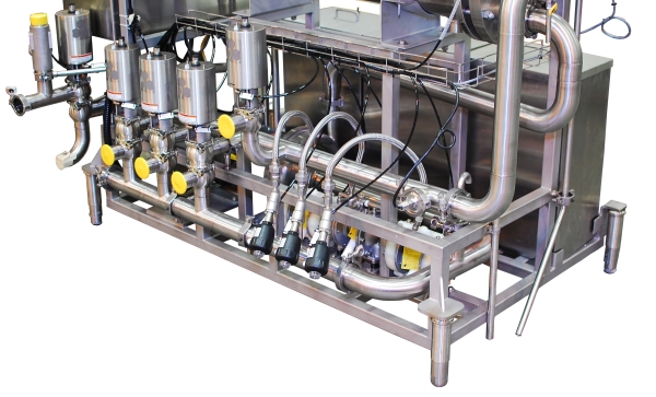
About 35 years ago leading manufacturers such as Federal Mfg. addressed the need for a new generation of CIP-based manufacturing and processes for high rotary fillers. Federal, for example, adopted guidelines established by the 3-A Standards Committee and developed CIP manifolds (wash rings) that allowed circulating solutions through the filling valves, and adapted spray balls to clean the inside of the filler bowl. These cleaning systems consisted of a centrifugal pump, several hand-operated divert valves and hoses to connect between the pump, valve manifolds, and a spray ball connection. The divert valves allowed cleaning solutions to be routed bi-directionally through the filling valves. These CIP methods were an improvement over hand cleaning, but further developments were needed to improve the basic elements of a successful cleaning and sanitizing program.
The role of time, temperature, flow, velocity, and solution concentration in effective CIP
The industry leaders began to focus on controlling the most basic requirements for effective cleaning. These now well-known elements are time, temperature, flow velocity, and solution concentration. A new system was developed with a skidded unit, which included a centrifugal pump, a stainless steel steam heating package, and sanitary, air-actuated divert valves to be used to route solutions bi-directionally through the filling valves. These systems were controlled through a small microprocessor or from the main filler’s programmable controller. Later an automated dosing system was incorporated to dispense liquid caustic, acid, and sanitizer. Eventually a conductivity sensor was added to monitor the acidity or alkalinity of the reagents to assure they were circulating at concentrations recommended by the supplier.
These systems were designed to ensure that a flow rate of 14 gallons per minute per valve was delivered to each valve manifold at the proper temperature and cleaning solution concentration. Interlocking safeties ensured that the system cannot be bypassed. For processors that have a goal of extending the code life beyond 18 to 20 days – normal for dairy – or 30 days for juice and cultured products – Federal, for example, developed the E-Series filling valve assembly. This valve assembly provides a means of cleaning the outside, as well as all product contact surfaces of the filling valve. With the E-Series valve, a sealed canister encapsulates the valve during cleaning. The valve and its mating valve flange are designed so that when the canister is installed, the valve is held in a full-open position, allowing a path for cleaning fluids to flow completely between the inner and outer valve sleeves and around the valve sealing ring and its groove. In addition, the canister allows the filling valve to be sanitized with a chemical sterilizer, hot water at 205° F, or with 50 psi steam, whichever method the application may require.
The use of the E-series filling valve with the CIP/sanitary-in-place (SIP) canister, coupled with a closed filler bowl can provide extended-shelf-life (ESL) that is not normally possible with a contact filler (i.e., a machine in which the container makes contact with the filling valve).
Some manufacturers thought they had a better and less costly method of building CIP systems. These manufacturers designed CIP systems in which the filling valves are opened with a cam-activated system to allow cleaning solution to flow through the valve by gravity. The design removed parts and simplified the machine, reducing its cost. This unidirectional, low-flow method is an effective way to quickly drain the bowl and expedite product changeovers. When used with high-acid products or neutral products not containing fats and oils, the gravity system provides adequate CIP.
The sterilization problem with gravity systems takes place when they are used to fill milk or milk products. This method reduces machine cost, but at the same time raises the risk of contamination, shorter shelf life, off taste, and lower overall production output. The reason for this goes back to the undisputable fact that effective cleaning is obtained by controlled and repeatable use of four independent variables:
- Time
- Temperature
- Flow velocity
- Solution concentration
The liquid must scour the machine
When only gravity is used as a motive force to move solution through a valve, one of the four important variables, flow velocity, has been removed from the effective CIP process. The importance of flow in equipment cleaning cannot be underestimated.
To be effective in CIP flow needs to be turbulent in order to scour surfaces, much as in the past when brush bristles were used for scouring. Turbulent flow is measured by engineers as a Reynolds number that exceeds 4,000. The Reynolds number gives a measure of the ratio of inertial forces to viscous forces. With a Reynolds number greater than 4,000, the flow of the CIP fluid does an effective scouring job.
The formula for calculating Reynolds number follows:
Where:
is the mean velocity of the object relative to the fluid (SI units: m/s)
is a characteristic linear dimension (travelled length of the fluid) (m)
is the dynamic viscosity of the fluid (Pa•s or N•s/m² or kg/(m•s))
is the kinematic viscosity ( ) (m²/s)
is the density of the fluid (kg/m³)
A flow rate of between 5 and 10 feet per second (1.5 to 3.0 meters per second) should generate a Reynolds number greater than 4,000 in a straight length of stainless steel sanitary tubing. When flows are measured within the 5 and 10 feet per second range, the flow is generally considered turbulent and thus provides good cleaning, scouring action. The gravity feed systems don’t come anywhere close this flow and scouring efficiency. This is especially true considering that the gravity CIP systems are cleaning a 14 inch straight run of filling valve vent tube and the complex contours found elsewhere within the valve. The flow is simply not sufficient.
Federal and one of its dairy customers decided to examine a gravity CIP system. After a few days of employing only time, temperature, detergent concentration, and unidirectional, gravity flow to clean the machine, the unit was inspected. The clean valve was removed from the filler bowl and dipped into water. Water was seen beaded up on the tube’s inside diameter, which meant there was un-removed milk fats and oils. One cannot argue with physics. The Reynolds number when calculated was well below 4,000 and the scouring action insufficient.
There are no mechanical or cost shortcuts to obtaining a high level of machine sanitation. CIP requires the following:
- Time
- Temperature
- Flow velocity
- Solution concentration
When investing in a filling machine, consult with the OEM’s engineers and ask them to detail how their approach to these four criteria ensures the 3A Sanitary Standard has been met and to make Reynolds number calculations.
Mike Collins has more than 20 years experience in the dairy business. He is vice president of sales and marketing for Federal Mfg. (a Pro Mach Business). Send comments to mcollins@federalmfg.com.


